12 Technical data
12.10.2 Time response of the digital outputs
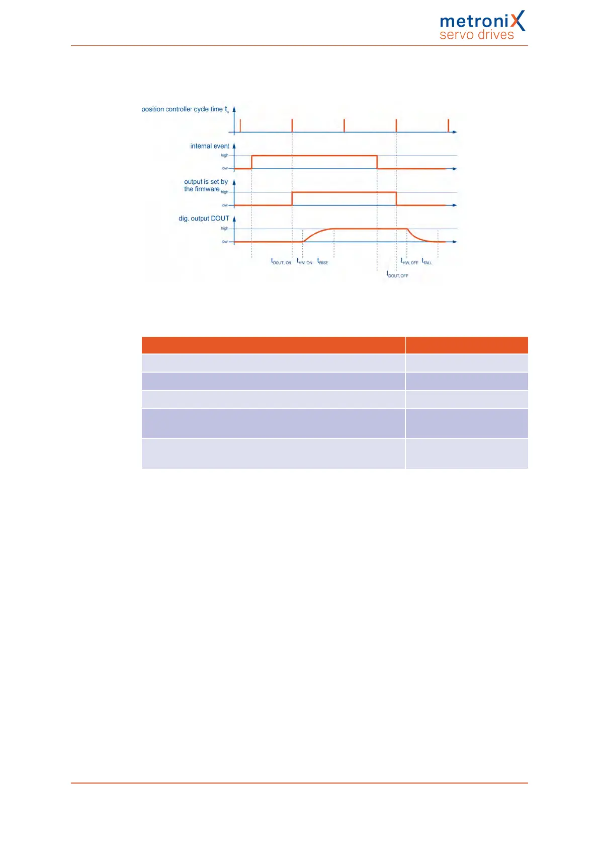
Figure 128: Filter time mechanism in the case of digital outputs
Parameter Value
Delay caused by the firmware t
DOUT_ON
/ t
DOUT_OFF
t
x
DOUTt
HW,ON
typically 100 µs
DOUT t
HW, OFF
typically 300 µs
t
RISE
typically 100 ms with 2 A
and inductive load
t
FALL
typically 100 ms with 2 A
and inductive load
t
x
= position controller cycle time (typically 200 µs with a current controller cycle time t
i
of
50 µs)
Product manual BL 4000-C Page 228 of 298
 Loading...

