3 Product description
3.2 Device view
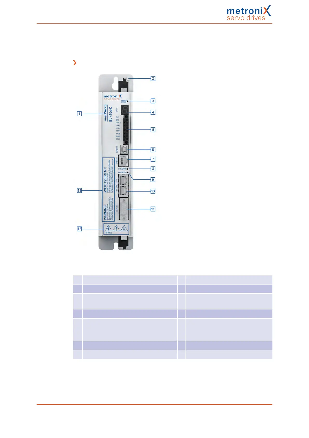
Front view
Figure 2: Front view
01 Product name 08 LED (RUN/SF/MS)
02 Earthing screw 09 LED (ERR/BF/MS)
03 Status indicator LED
(READY, ERROR, ENABLE)
10 [X21] Real-time Ethernet interface
04 Seven-segment status indicator 11 [X4] CANopen interface
05 [X3] STO interface (STOA, STOB),
Limit switch (DIN6, DIN7),
Dig. output (DOUT0)
12 Safety Symbols as per ISO7000
06 [X19] USB interface 13 Warnings
07 [X18] Ethernet interface
Product manual BL 4000-C Page 25 of 298
 Loading...

