13 Electrical installation
13.10 Connector: CAN bus [X4]
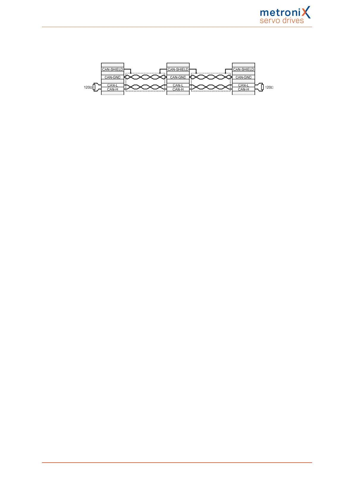
Figure 144: CAN bus cabling example
l Ideally, the individual nodes of the networks are always connected in a linear
manner so that the CAN cable is looped through from servo drive to servo drive.
l
A terminating resistor of 120 Ω, 5%, must be present on both ends of the CAN bus
cable.
l Shielded cables with exactly two twisted pairs must be used for cabling.
l Use one twisted pair to connect CAN-H and CAN-L.
l The cores of the other pair are used jointly for CAN-GND.
l The shield of the cable is led to the CAN shield connections for all nodes.
l We advise against the use of plug adaptors for cabling the CAN bus. However, if
this is necessary, use metal connector housings for connecting the cable shield.
In order to keep interferences as low as possible ensure that
l the motor cables are not installed parallel to signal lines
l the motor cables comply with the Metronix specification
l the motor cables are properly shielded and earthed (grounded)
Product manual BL 4000-C Page 253 of 298
 Loading...

