13 Electrical installation
13.9 Connector: real-time Ethernet [X21]
The connection to an EtherCAT or PROFINET network must be realised via two female
RJ45 connectors. Details can be found in the Fieldbus manuals.
Configuration on the device [X21]
Female RJ45 connector, cat. 6
Mating connector [X21]
Male RJ45 connector
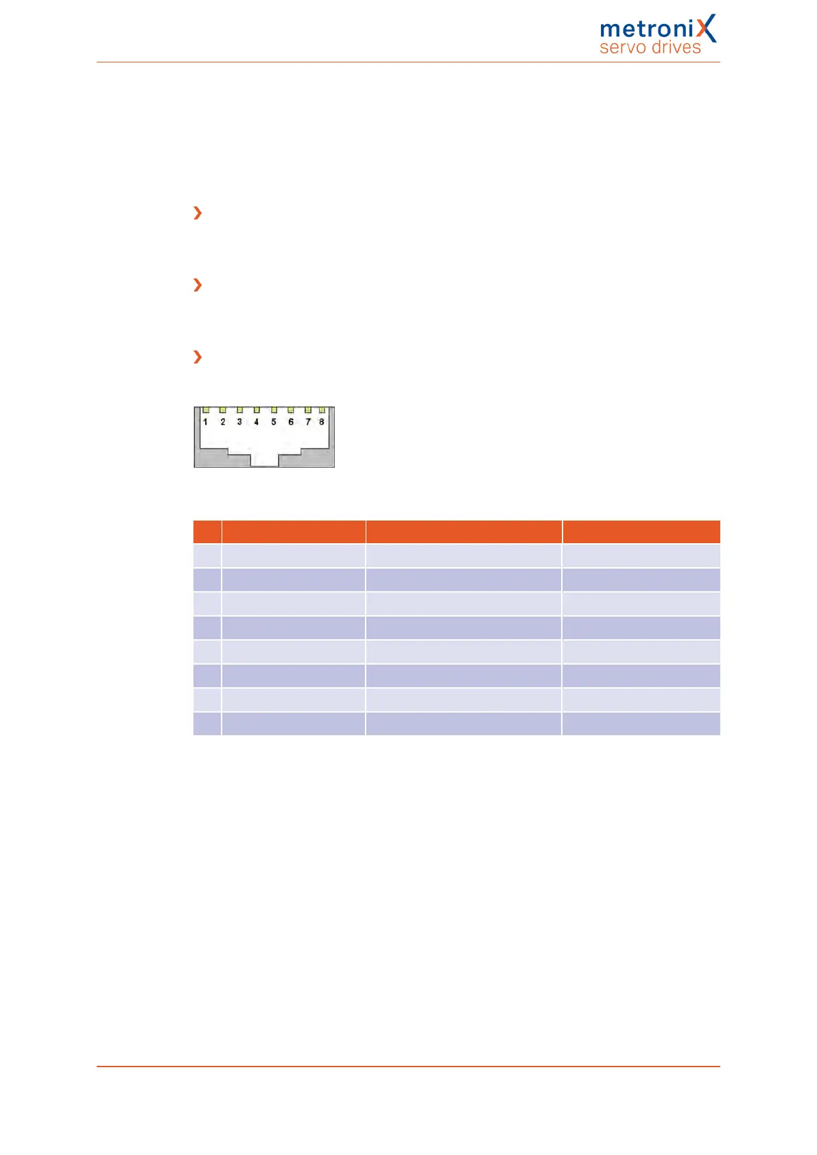
Pin assignment of the real-time Ethernet connector [X21]
Cat.6 patch cable RJ45 LAN cable S-FTP/PIMF.
Figure 143: Pin assignment of the real-time Ethernet connector
Pin Name Description Colour
1 TX+ Transmission signal + Yellow
2 TX- Transmission signal - Orange
3 RX+ Reception signal + White
4 - -
5 - -
6 RX- Reception signal - Blue
7 - -
8 - -
Product manual BL 4000-C Page 252 of 298
 Loading...

