13 Electrical installation
13.3 Connector: power supply [X9]
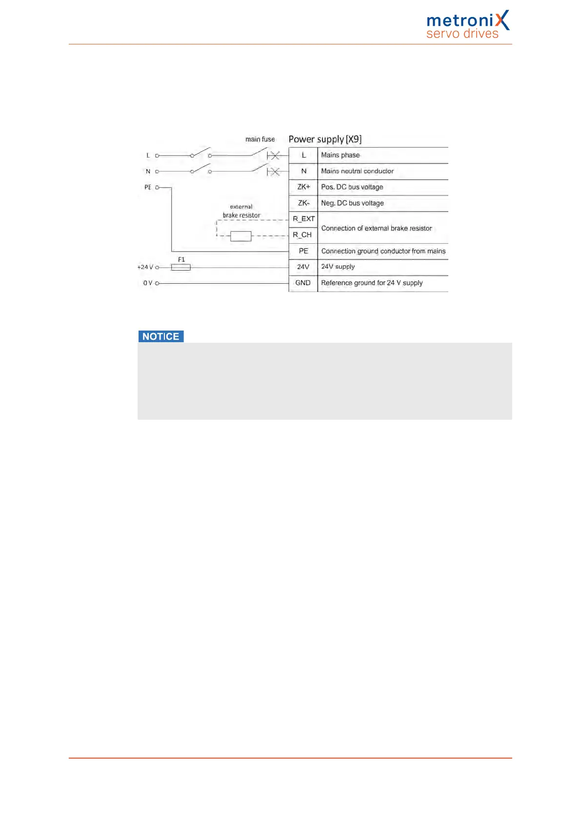
Servo drives of the BL4100-C series must be connected to the voltage supply and an
optional brake resistor in accordance with the following illustration.
Figure 132: Connection to the power supply [X9]
Risk of damage to the servo drive
The servo drive will be damaged in the following cases:
l reverse connection of the 24 V operating voltage connections,
l excessive operating voltage, or
l accidental interchanging of the operating voltage and motor connectors.
A 24 V supply and a single-phase mains power supply are required for operation. Direct
DC coupling of the DC buses of several devices is possible by way of the terminals ZK+
and ZK-. The terminals MT+ and MT- can be used for the connection of a motor
temperature sensor (NTC/PTC or normally closed contact). A shaft encoder can be
connected via the D-Sub connector at [X2A]/[X2B]. If motors with a Hiperface DSL
encoder are used, this encoder must be connected via [X6].
The servo drive must be connected to earth (ground) with its PE connectors.
First, wire the servo drive completely. Then, switch on the 24 V supply and the mains
power supply.
The servo drive has an internal brake chopper and braking resistor. For more braking
power, an external braking resistor can be connected to the connector [X9].
Product manual BL 4000-C Page 239 of 298
 Loading...

