13 Electrical installation
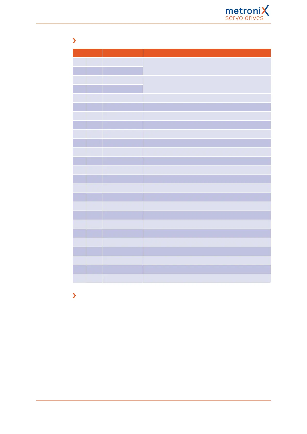
Pin assignment [X1]
Pin Name Specification
1 #AIN1 Analogue input 1, input voltage 30 V max.
14 AIN1
2 #AIN0 Analogue input 0, input voltage 30 V max.
15 AIN0
3 A / CLK Incremental encoder signal A/stepper motor signal CLK
16 A# / CLK Incremental encoder signal A#/stepper motor signal CLK
4 B / DIR Incremental encoder signal B/stepper motor signal DIR
17 B# / DIR Incremental encoder signal B#/stepper motor signal DIR
5 N Incremental encoder index pulse N
18 #N Incremental encoder index pulse N#
6 GND24 Reference potential for I/Os at X1
19 DIN0 Digital input 0 (target 0)
7 DIN1 Digital input 1 (target 1)
20 DIN2 Digital input 2 (target 2)
8 DIN3 Digital input 3 (target 3)
21 DIN4 Digital input 4 (input)
9 DIN5 Digital input 5 (servo drive enable signal)
22 DIN6 Digital input 6 (limit switch 0)
10 DIN7 Digital input 7 (limit switch 1)
23 DIN8 Input (flying saw)
11 5 V Encoder supply (see pin 3 to 18)
24 24 V Auxiliary voltage for I/Os at X1
12 DOUT0 Freely programmable output
25 DOUT1 Freely programmable output
13 DOUT2 Freely programmable output
Cable type and configuration [X1]
The cable name that is stated refers to a cable made by Lapp. However, it is also possible
to use comparable cables from other manufacturers, for example Lütze or Helukabel.
LAPP KABEL UNITRONIC LiYCY (TP); 25 x 0.25mm²
Product manual BL 4000-C Page 256 of 298
 Loading...

