1 Overview
11
1.4 Nomenclatures and functions
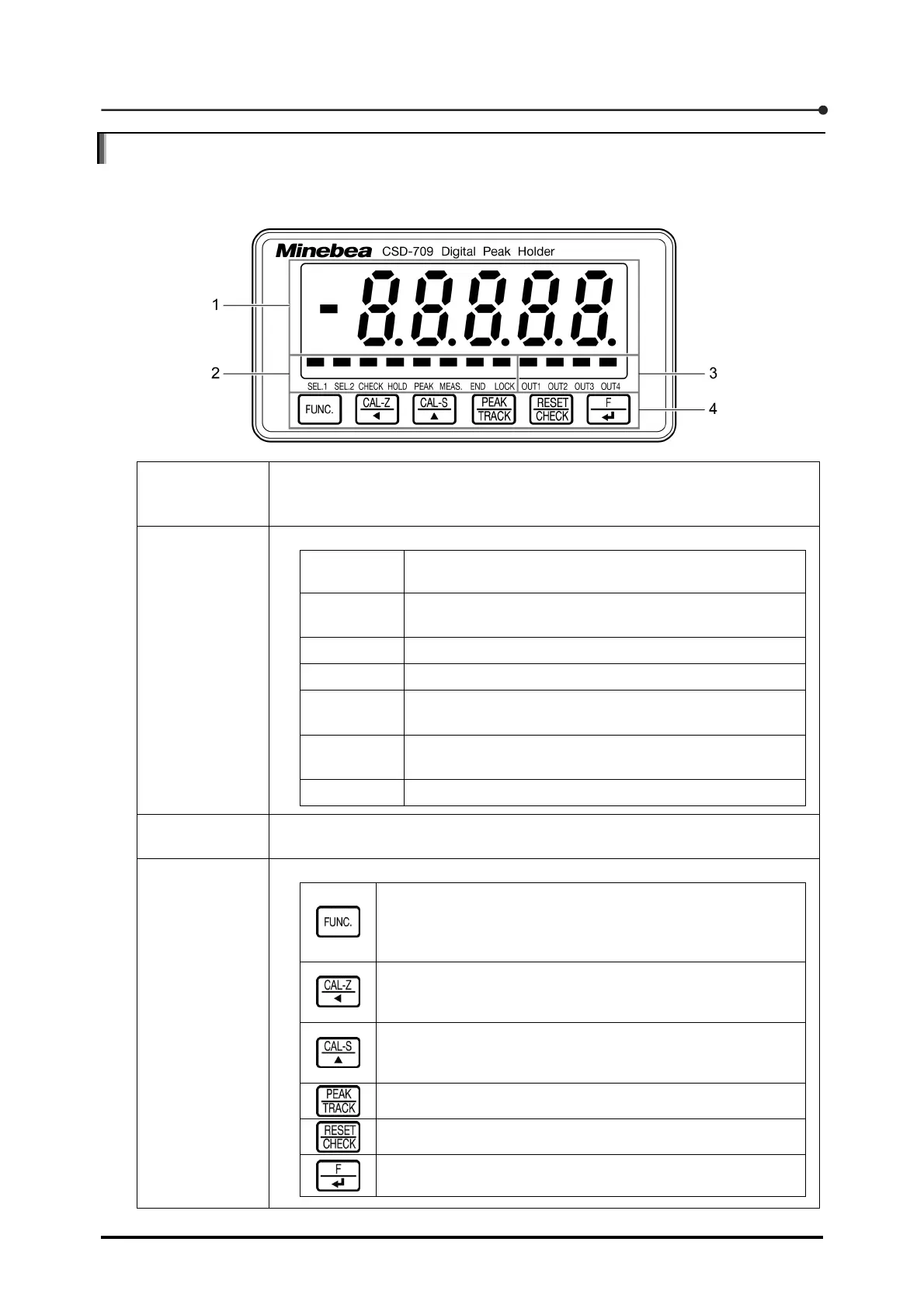
1.4.1 Front panel
1. Load window
Indicates the value currently measured in Measurement mode. Also indicates
the settings in any mode other than Measurement mode, such as Function
mode.
2. Status
window
Indicates the current condition by turning on the associated LED.
SEL1, SEL2
Either LED is turned on depending on the calibration
number selected.
CHECK
This LED is turned on while the check value is being
output.
HOLD This LED is turned on in hold mode.
PEAK This LED is turned on during detection of a peak.
MEAS.
This LED is turned on during detection of a peak in a
section other than reset section.
END
This LED is turned on during detection of a peak in the
hold mode.
LOCK This LED is turned on in the key lock mode.
3. Judgment
window
Indicates the condition of the selected external control output by turning on the
associated LED.
4. Key
Inputs commands necessary for settings and operations.
Selects any mode other than Measurement mode, such as
Function mode. Holding this key down for at least two
seconds triggers simplified numerical value input based
calibration.
Allows you to move to the next upper digit in the target
setting. Holding this key down for at least two seconds
triggers simplified zero calibration.
Increases the numerical value of the target setting by one.
Holding this key down for at least two seconds triggers
simplified span calibration.
Selects the track or various peak detections.
Resets the peak. Also outputs the CHECK value.
Executes the F key operation already set. Also registers the
setting.