J Communications Based on Modbus Protocol
191
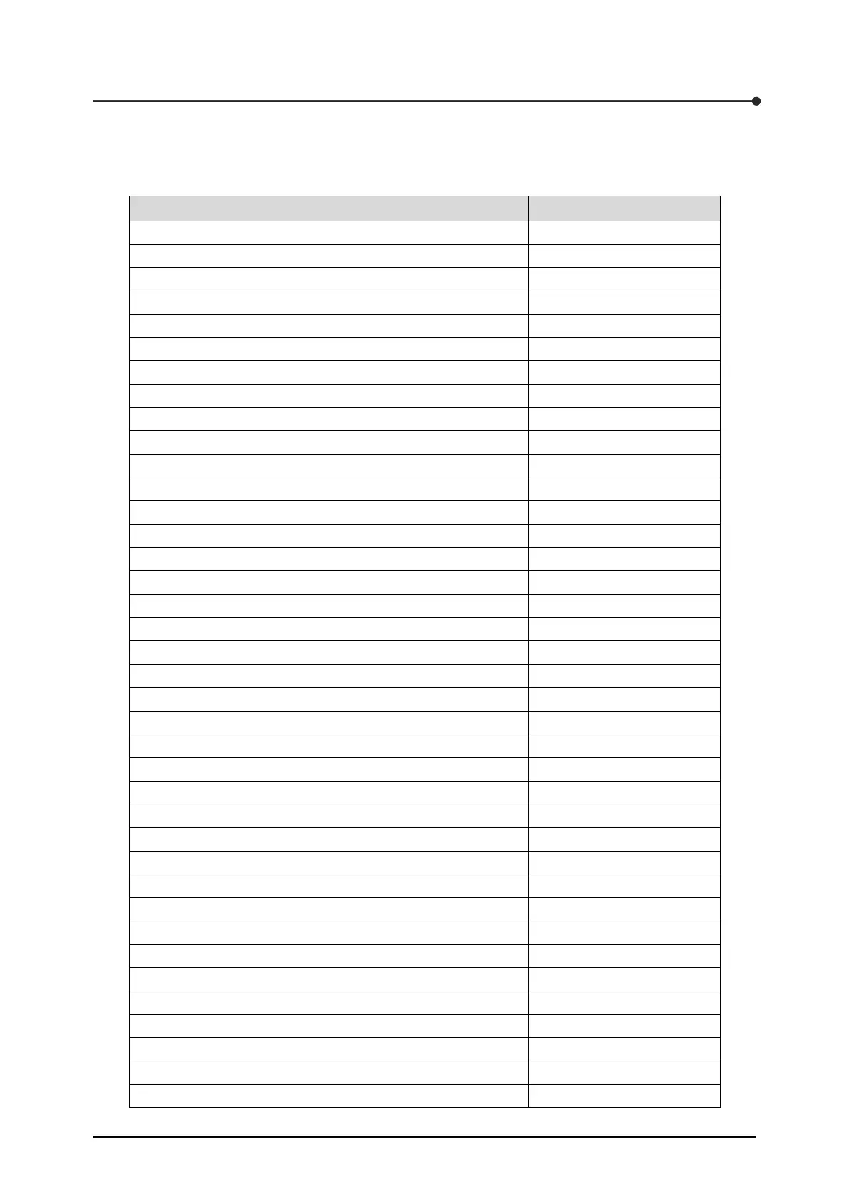
J.3.4 Hold register
The hold register offers reference and change functions using a 16-bit length word. Shown below is
the data that can be referenced and changed by the hold register.
Data Address
S0 (Calibration number 0) 11
S1 (Calibration number 0) 13
S2 (Calibration number 0) 15
S0 (Calibration number 1) 267 ~ 268
S1 (Calibration number 1) 269 ~ 270
S2 (Calibration number 1) 271 ~ 272
S0 (Calibration number 2) 523 ~ 524
S1 (Calibration number 2) 525 ~ 526
S2 (Calibration number 2) 527 ~ 528
S0 (Calibration number 3) 779 ~ 780
S1 (Calibration number 3) 781 ~ 782
S2 (Calibration number 3) 783 ~ 784
Calibration number 53249
Operating modes 56833
Unit weight 56835 ~ 56836
Setting of measuring weight 56837 ~ 56838
Setting of weight mass 56839 ~ 56840
Registration of zero point load cell output 56841 ~ 56842
Registration of span point load cell output 56843 ~ 56844
Actual load based calibration — Under AD reading 56845
Actual load based calibration — Registration of zero point 56846
Actual load based calibration — Registration of span point 56847
Calibration complete 56848
Zero point fine adjustment 56849
Span point fine adjustment 56850
Fine adjustment mode, load display 56857 ~ 56858
Function 1 57345
Function 1 57346
Function 2 57347
Function 2 57348
Function 3 57349
Function 3 57350
Function 4 ~ 98 57351 ~ 57542
Function 99 57543
Function 99 57544
C function 1 57857
C function 1 57858
C function 2 57859