FIXING UNIT
2 - S - 8
Wiring band
Connector (CN98)
Set screw
Pin 4
Pin 3
Pin 2
Pin 1
Set screw
Wiring band
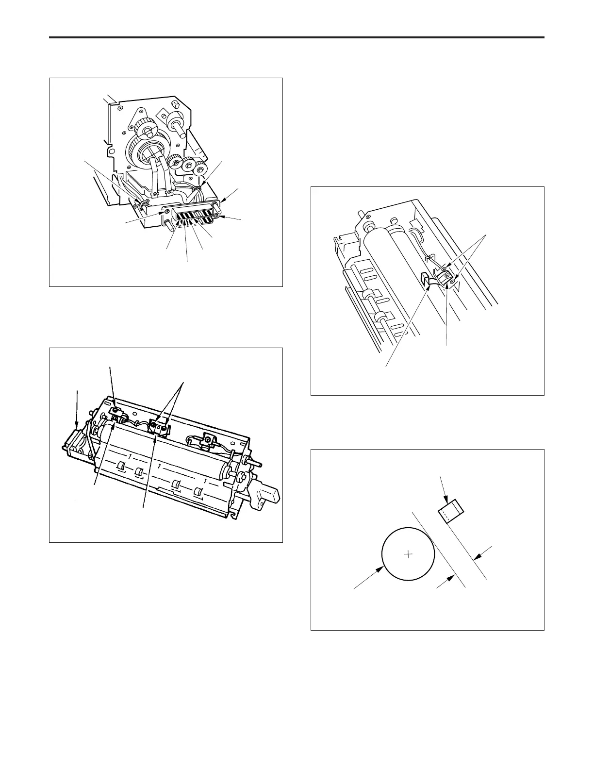
(4) Remove the two set screws, then remove fixing tem-
perature sensor 1.
(5) Remove the set screw, then remove fixing tempera-
ture sensor 2.
b. Installation procedure
(1) Secure fixing temperature sensor 2 with the set screw,
so the sensor element is in contact with the upper fixing
roller.
(2) Set the fixing temperature sensor positioning jig be-
tween fixing temperature sensor 1 and the upper fixing
roller, then fix fixing temperature sensor 1 with two set
screws so that the clearance between the sensor and
the upper fixing roller is within the standard value.
(a) Set the distance “a” between the upper fixing roller
and fixing temperature sensor 1 so that it is equal
to the thickness of the fixing temperature sensor
positioning jig.
a
(3) Coat the set screw of each sensor with paint lock
agent.
(4) Insert the connector pins on the end of the cable of
each sensor to a position that corresponds to CN98.
(5) Re-install the other parts in the opposite sequence to
removal.
Upper fixing roller
Fixing temperature sensor 1
Fixing temperature
sensor 2
Fixing temperature sensor 1
Connector
(CN98)
Set screw
Set screws
Set screws
Fixing temperature sensor 1
Fixing temperature sensor positioning jig
Standard: a = 0.7 ± 0.03 mm
FIXING UNIT-1