2 - S - 9
FIXING UNIT
11.Removing and Re-installing Fixing
Temperature Sensor 3
Caution:
1. After re-installing fixing temperature sensor 3 ,
check to ensure that the sensor wires are not
touching the upper fixing roller.
2. Be sure to coat the set screws of the sensors with
screw lock agent after re-installing the sensors.
a. Removal procedure
(1) Remove the upper paper exit roller unit, upper fixing
cover, oil pad, oil apply roller and entrance guide plate
(lower).
(2) Cut the a wiring band, then release the relay connector
of the temperature sensor 3.
(3) Remove the two set screws, then remove fixing tem-
perature sensor 3.
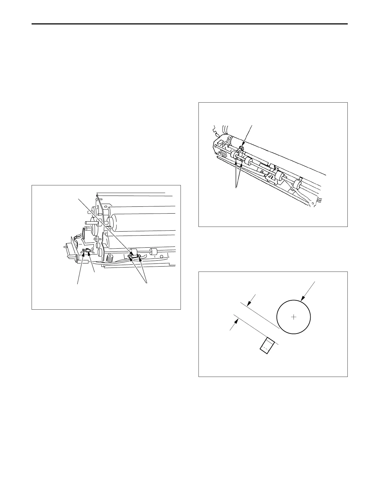
b. Installation procedure
(1) Set the fixing temperature sensor positioning jig be-
tween fixing temperature sensor 3 and the upper fixing
roller, then fix fixing temperature sensor 3 with two set
screws so that the clearance between the sensor and
the lower fixing roller is within the standard value.
Set screws
Fixing temperature sensor positioning jig
(for lower loller)
(a) Set the distance “b” between the upper fixing roller
and fixing temperature sensor 3 so that it is equal
to the thickness of the fixing tempera ture sensor
positioning jig.
Lower fixing roller
Fixing temperature sensor 3
b
Standard: b = 1.75 ± 0.25 mm
Temperature
sensor 3
Relay connector
Set screws
Wiring band