5 - 15
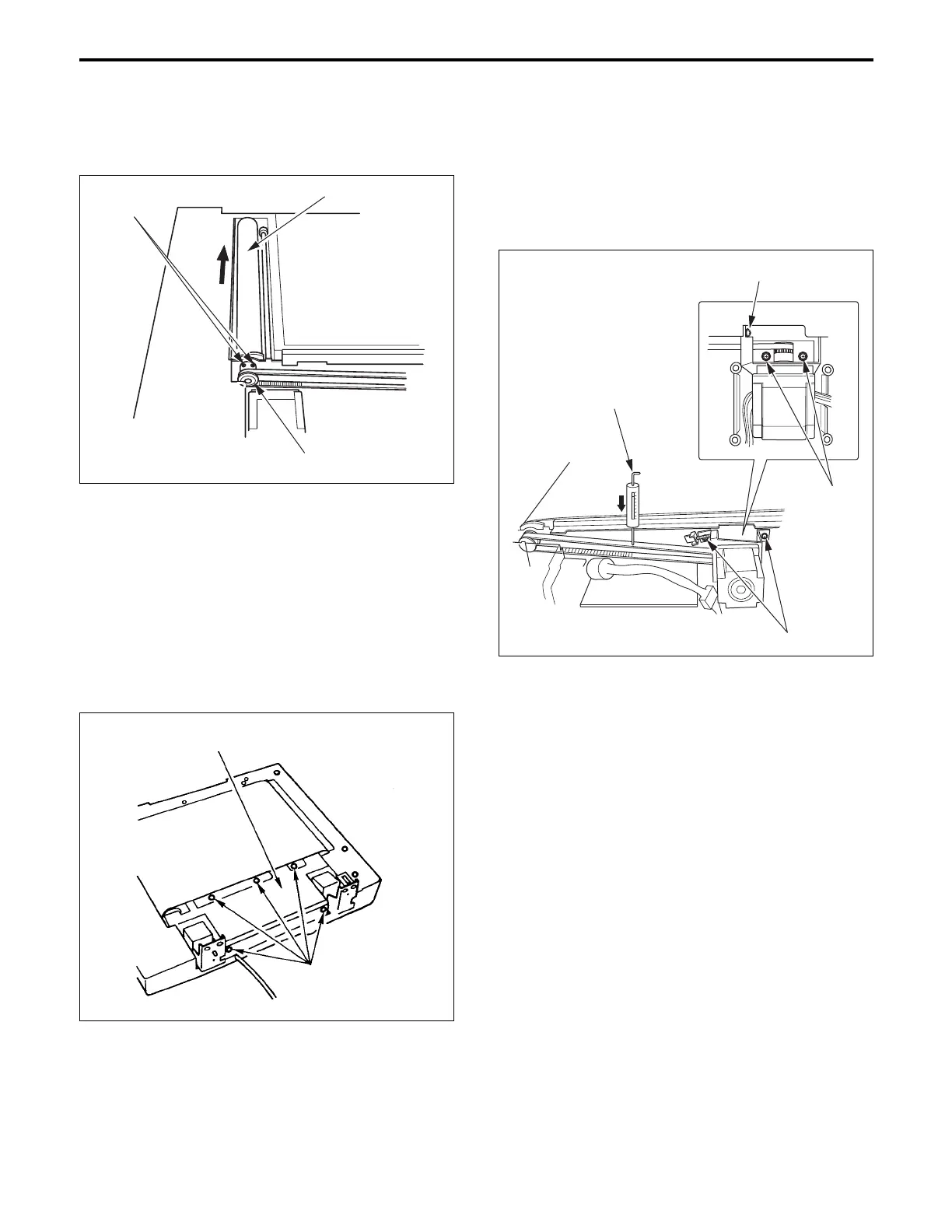
(4) Slacken the two hex socket screws then remove the
drive roller in the direction of the arrow.
Hex socket
screws
Drive roller
Conveyance pulley
(3) Slacken the four set screws of the conveyance motor
(M302).
(4) Press the tension gauge (full scale 300g) against the
center of the timing belrt.
(5)
When the belt bend value is 5 mm, adjust the tension
adjusting screw so that it is within specifications.
Set screws
Set screw
Standard: 200g ± 20g
(when belt bend value is 5mm)
Tension adjusting screws
Tension gauge
(6) Tighten the set screw of the conveyance motor.
(7) Re-install the above parts in the opposite sequence to
removal.
(6) Re-install the above parts in the opposite sequence to
removal.
Set screws
Body base plate (C)
4. Adjusting the tension of conveyance drive
timing belt
a. Procedure
(1) Remove the ADF unit from the main body.
(2) Remove the five set screws, then remove the Body
base plate (C).