2 - F - 7
WRITE UNIT
determines the laser write start timing for each scan in
the axial direction of the drum.
b) Direction of rotation of drum
1) When very high is selected
When PS4 (paper feed start) is ON.
2) When data is output from the E-RDH memory
When the copy paper reaches the specified
position
*
In the case of paper feed from the tray, LCT or
ADU:
After the specified period from when PS18 (no
feed) goes ON
* In the case of by-pass paper feed:
After the specified period from the start of by-
pass paper feed
(3) Laser beam position correction
a) Axial direction of drum
The index sensor detects the deviation of the
positions of the 2 beams. This error is corrected by
changing the timing of the light emission from the
laser.
b) Direction of rotation of drum
The index sensor detects the deviation of the
positions of the 2 beams, and M40 (laser correction
motor) changes the angle of the fine adjustment
prism of laser LD1, thus adjusting the beam in the
up-down direction.
2. Signals
a. CB output signals
(1) MEE V/V (CB → IPB)
This signal determines the scanning area in the sub
scanning direction during the pre-scanning operation
(AES control). The period during which this signal is [L]
is judged as the scanning range.
(2) MS V/V (CB → IPB)
This signal determines the scanning range in the sub
scanning direction during the exposure scan. The
period over which this signal is [L] is judged as the
scanning range.
(3) DC 0 RR (CB → IPB)
Black data
collection
trigger used when shading col-
lection is taking place.
(4) I YOBI 1 (CB → IPB)
Spare input port
(5) RXA 0, 1 (CB → IPB)
Data that is transferred serially from the CB to the IPB
(6) MTN V/V (CB → IPB)
This signal determines the patch output range in the
sub scanning direction while Dmax is being measured.
The period during which this signal is [L] is judged as
the patch output range.
(7) MAPC CAL (CB → IPB)
APC and PWM calibration trigger signal
The following processing is performed by the E-RDH
(electronic RDH processing board).
a) Error diffusion processing
b) Data compression and de-compression
c) Image rotation
d) Combination (2-in-1, 4-in-1, 8-in-1)
The write operation takes place under instructions from the
CB after the above processing has been completed.
b. Write
The IPB (image processing board) sends image data one
pixel at a time to LDB1 and LDB2 in accordance with control
signals from the CB (control board).
LDB1 and LDB2 cause the lasers to emit at a time period
corresponding to the image data. This laser light is applied
to the drum.
(1) APC (automatic adjustment of laser beam intensity)
The CB monitors the laser drive current at fixed inter-
vals, and maintains the light intensity at the correct
value.
APC takes place at the following timing.
a) Before Dmax/gradation correction
b) When the
Start Print
button is pressed
c) After each two copies during a continuous copy
operation
d) When the front door is opened and closed.
Note: MPC
MPC is the data (00-99 steps)stored in the NVRAM in
main body, which determines LD output power to be
adjusted later by APC.
Can be read out by 47-036, 47-037.
MPC value is sent from CB to IPB in case of a) or
b) in (1).
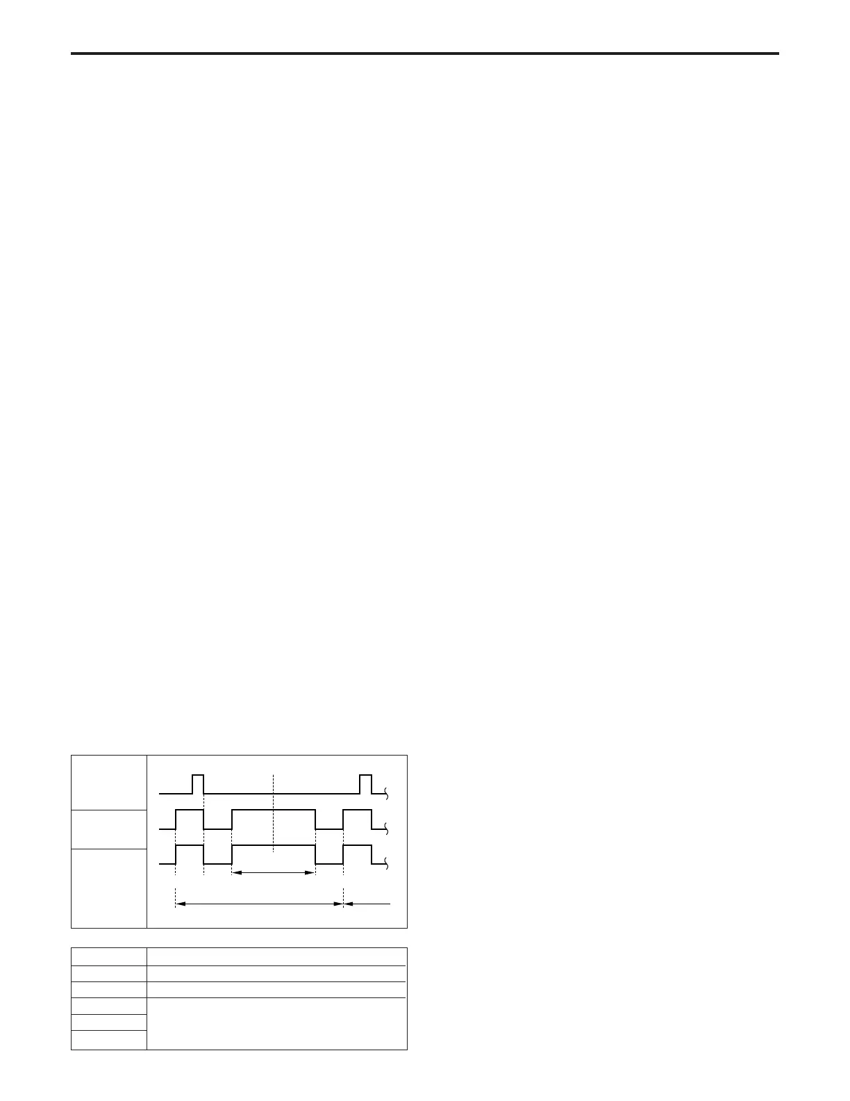
(2)Write Timing
a) Axial direction of drum
In this machine, the INDEX signal from INDEXSB
abc de
Image area
Laser
ouintput 1
Laser output
2
1st scan
2nd scan
Symbol
a
b
b–c
c–d
d–e
Description
When laser goes ON during 1st scan
When index sensor goes ON
The timing at left is controlled by counting the
LD1 IRCLK and LD2 IRCLK signals. It differs
depending upon the paper size.
INDEX
WRITE UNIT-1