SHOP MANUAL MT26/31 - 08.2006 SHOP MANUAL MT26/31 - 08.2006
SHOP MANUAL MT26/31 - 08.2006 SHOP MANUAL MT26/31 - 08.2006
TRANSMISSION
Ch 2 page 106 Ch 2 page 107
TRANSMISSION
TRANSMISSION
Ch 2 page 106 Ch 2 page 107
TRANSMISSION
Pre-assemble opposite side
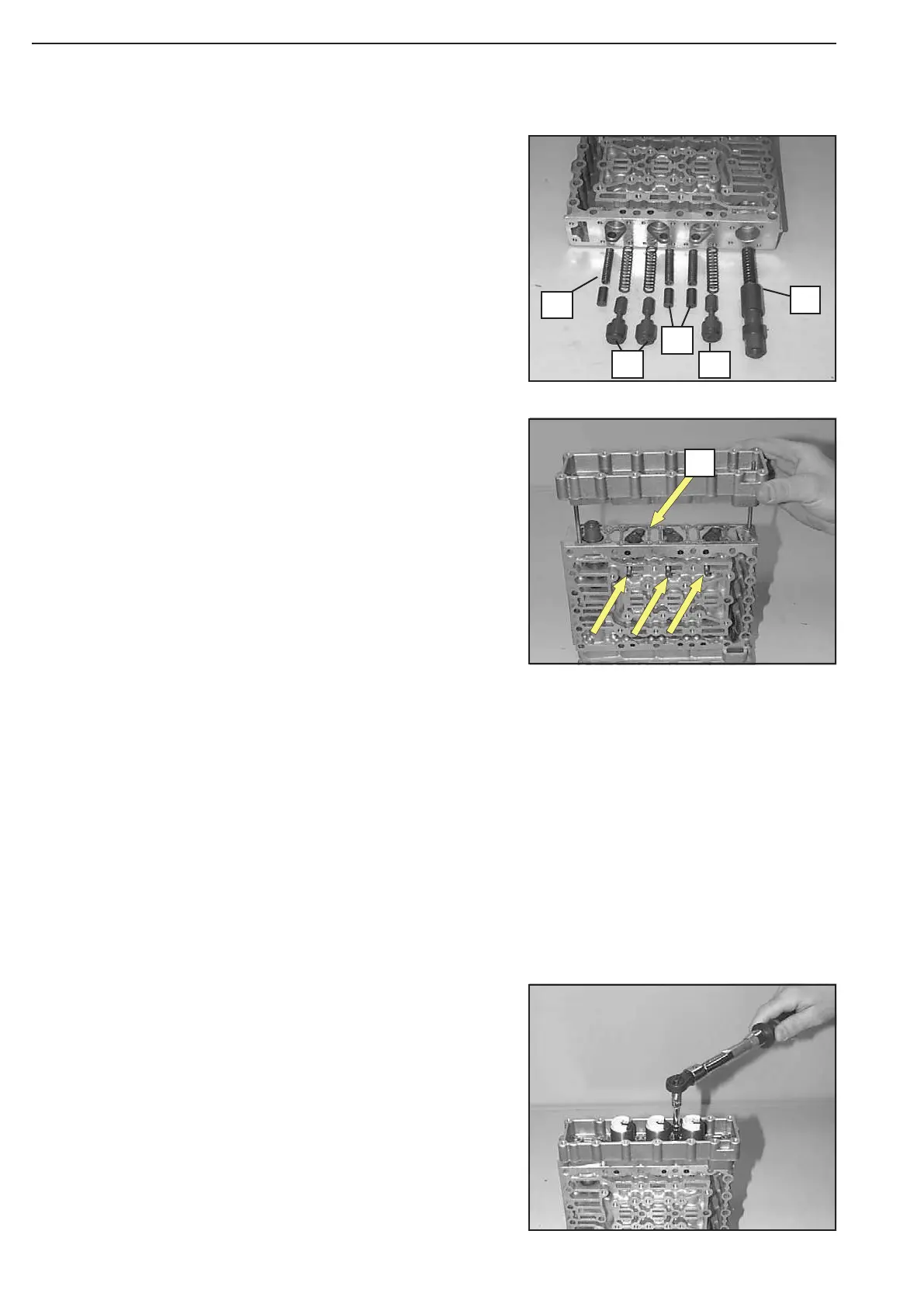
The Figure on the left shows the following components:
1 = Main pressure valve (1x spool and compression spring)
2 = Follow-on slide (3x spool and compression spring)
3 = Vibration damper (3x spool and compression spring
Introduce pressure regulators and fix them by means of
retain-ing plates and socket head screws.
Install retaining plates, with the claw showing downward !
Pay attention to the radial installation position of the pres-sure
regulators, see Figure !
Torque limit .................................... 5,5 Nm
Now, fasten housing cover by means of socket head screws.
Torque limit ..................................... 5,5 Nm
Remove cylindrical pins (assembly aid) again.
(S) Adjusting screws 504188
Install components according to Figure 21.
Preload compression springs of the follow-on slides and fix
the spools provisionally with cylindrical pins Æ 5 mm
(assembly aid), see Arrows !
Install two adjusting screws.
Line up flat gasket (Arrow 1) and housing cover and bring
them uniformly against shoulder, using adjusting screws.
Figure 21
Figure 23
Figure 22
1
3
2
2
3
1