SHOP MANUAL MT26/31 - 08.2006 SHOP MANUAL MT26/31 - 08.2006
SHOP MANUAL MT26/31 - 08.2006 SHOP MANUAL MT26/31 - 08.2006
TRANSMISSION
Ch 2 page 192 Ch 2 page 193
TRANSMISSION
TRANSMISSION
Ch 2 page 192 Ch 2 page 193
TRANSMISSION
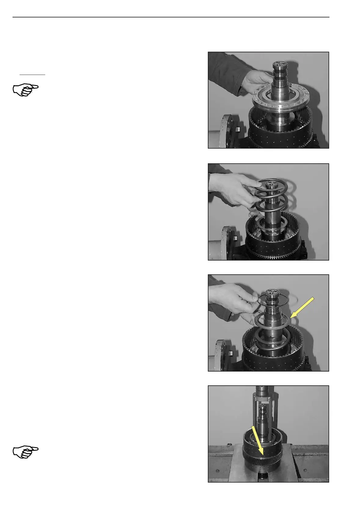
Figure 243
Figure 246
Figure 245
Figure 244
Oil O-rings and piston bearing surfaces.
Uniformly insert piston K3 until contact is obtained.
Observe the installation position of the
piston, see Figure!
Lift plate carrier out of the clamping ring.
Pre-load compression spring by means of special device (S) and
squeeze snap ring into the annular groove of the plate carrier (ar
-
row)
(S) Special device 504211
Analogously install purge valve, spool and
compression spring on the opposite side (clutch
K4).
Now, lift plate carrier with the K4-side showing downwards into the
clamping ring and fix it.
Tilt plate carrier by 180°.
Lay guide ring with the chamfer (arrow) showing upwards over
compression spring and line up snap ring.
Introduce intermediate washer and compression spring.