TRANSMISSION
Ch 2 page 214 Ch 2 page 215
TRANSMISSION
SHOP MANUAL MT26/31 - 08.2006 SHOP MANUAL MT26/31 - 08.2006
TRANSMISSION
Ch 2 page 214 Ch 2 page 215
TRANSMISSION
SHOP MANUAL MT26/31 - 08.2006 SHOP MANUAL MT26/31 - 08.2006
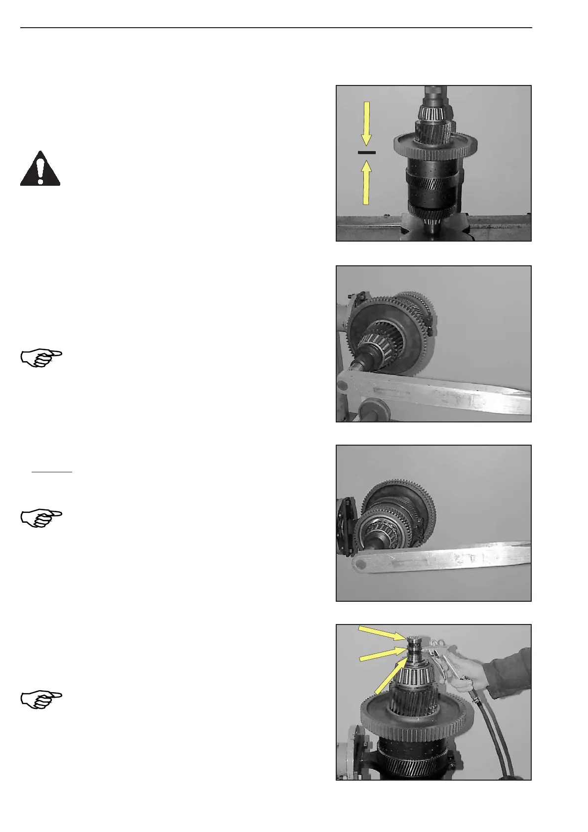
Figure 314
Figure 317
Figure 316
Figure 315
Lift plate carrier off the clamping ring (S).
To ensure the exact contact of the components, pre-load bearing
with 100 000 N (10 t) (Figure 314).
Support at the lower as well as the upper
bearing race!
Use pressure piece (S)!
(S) Pressure pieces 504218
Check functioning of clutches-K3 and K4 with compressed air
(Figure 317).
At correctly installed components, engaging
and disengaging of the clutch is clearly
audible!
Squeeze in and engage rectangular ring (3x, see arrow).
KR-side:
Wet thread of the slotted nut with Loctite (type-no. 262) and mount
it.
Install slotted nut with the collar (
Ø 76 mm)
facing the bearing inner race!
Torque limit ..................................... = 800 Nm
(S) Hook spanner 504215
Lift plate carrier into clamping ring (S) and fix it.
Tilt clutch 90°.
K2-side:
Wet thread of the slotted nut with Loctite (type-no. 262) and
mount it (Figure 315).
Install slotted nut with the chamfer facing the
bearing inner race!
Torque limit ..................................... = 800 Nm
(S) Clamping ring 504226
Or 504227
(S) Hook spanner 504215