TRANSMISSION
Ch 2 page 228 Ch 2 page 229
TRANSMISSION
SHOP MANUAL MT26/31 - 08.2006 SHOP MANUAL MT26/31 - 08.2006
TRANSMISSION
Ch 2 page 228 Ch 2 page 229
TRANSMISSION
SHOP MANUAL MT26/31 - 08.2006 SHOP MANUAL MT26/31 - 08.2006
Figure 369
Figure 372
Figure 371
Figure 370
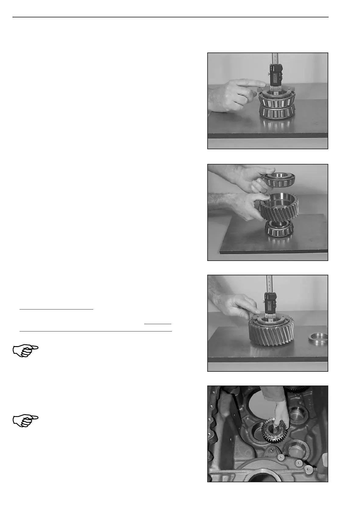
Determine measure I.
Measure I e.g.. ........................................ 61,85 mm
(S) Digital depth gauge 504175
Install components according to Figure 367 and position counter-
shaft gear inside the housing.
The assembly of the countershaft axle can be
performed only after the installation of the
clutches!
Repeatedly rotate countershaft gear to ensure centering of the
components
Determine measure II (total height without adjusting ring) .
Measure II e.g. ......................................... 61,82 mm
CALCULATION EXAMPLE:
Measure I ................................................. 61,85 mm
Measure II ..............................................
− 61,82 mm
Difference = Axial gap 0,03 mm
Measure I must be larger than measure II!
In case of deviations from the required axial
gap, correct with suitable shim!
Position countershaft gear over lower bearing inner race and place
upper bearing inner race on top.