SHOP MANUAL MT26/31 - 08.2006 SHOP MANUAL MT26/31 - 08.2006
SHOP MANUAL MT26/31 - 08.2006 SHOP MANUAL MT26/31 - 08.2006
TRANSMISSION
Ch 2 page 260 Ch 2 page 261
TRANSMISSION
TRANSMISSION
Ch 2 page 260 Ch 2 page 261
TRANSMISSION
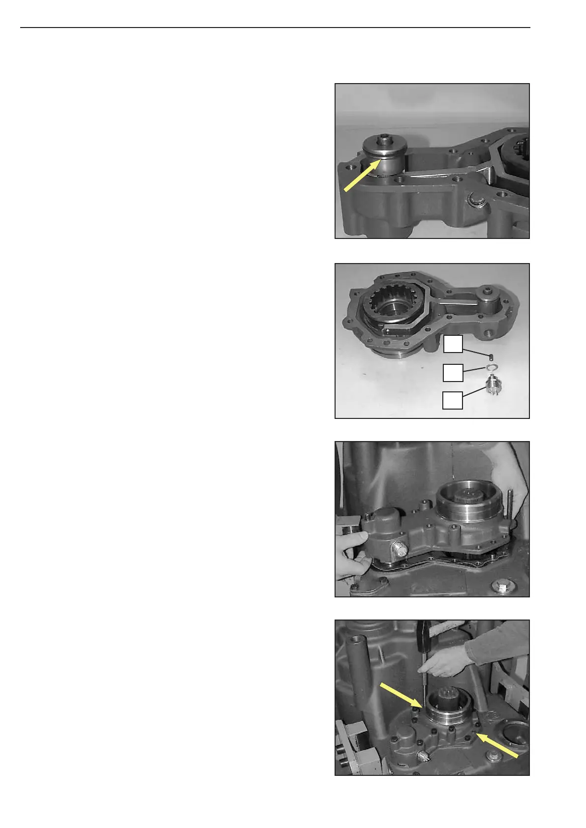
Figure 471
Figure 474
Figure 473
Figure 472
Introduce rectangular ring (VITON) into the annular groove of
the piston (arrow) and oil it.
Insert both socket head screws (arrows) until contact is ob-
tained.
Tighten hex. head screws and socket head screws.
Torque limit (M10/8.8) .............. M
A
= 46 Nm
Install two adjusting screws and mount flat gasket.
Heat up ball bearing, carefully introduce axle disconnection de
-
vice and uniformly position it against shoulder using hex. head
screws and socket head screws.
(S) Adjusting screws 504184
Mount switch.
1 = Lock
2 = Sealing ring (s = 1,5 mm)
3 = Switch
1
3
2