NXP Semiconductors
UM11227
NTM88 family of tire pressure monitor sensors
UM11227 All information provided in this document is subject to legal disclaimers. © NXP B.V. 2020. All rights reserved.
User manual Rev. 6 — 24 April 2020
123 / 205
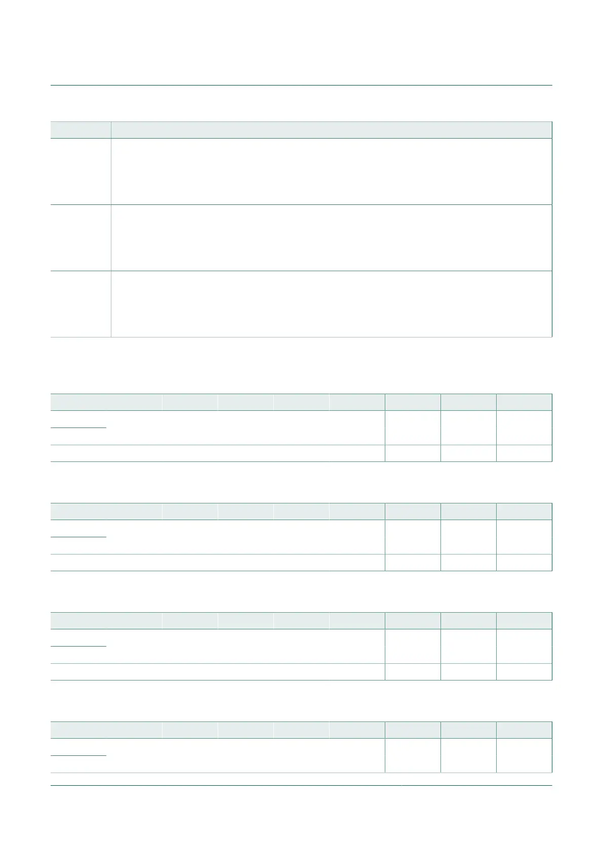
Field Description
2
RFLVDEN
RFLVDEN – RF Low Voltage Detect Enable Control
When the RFLVDEN bit is set, the RF LVD circuit will be enabled, and the RF LVD events are routed to the
RF LVD Trigger Flag. This bit is cleared by the RFMRST signal.
0 = RF LVD disabled; Result of Reset
1 = RF LVD enabled.
1
RCTS
RCTS – RF Clear To Send Status Flag
When the RCTS bit is set the RF XCO, VCO and PLL have started and locked and the RFM is ready to
send data. This bit is cleared by the RFMRST signal.
0 = RFM not ready to send; Result of Reset
1 = RFM ready to send.
0
RFMRST
RFMRST – RFM Reset Control
Writing a one to the RFMRST bit will completely reset the RFM and its registers. This bit is not affected by a
reset of the MCU. This bit will always read as a zero.
0 = No effect; Result of Reset
1 = Reset RFM.
10.16.11.9 RFM phase lock loop control registers 0 through 3 (PLLCR0 / PLLCR1 / PLLCR2 /
PLLCR3)
Table 119. RFM phase lock loop control register 0 (PLLCR0) (address $1838)
Bit 15 14 13 12 11 10 9 8
R
W
AFREQ12 AFREQ11 AFREQ10 AFREQ9 AFREQ8 AFREQ7 AFREQ6 AFREQ5
Reset 0 0 0 0 0 0 0 0
Table 120. RFM phase lock loop control register 1 (PLCCR1) (address $1839)
Bit 7 6 5 4 3 2 1 0
R
W
AFREQ4 AFREQ3 AFREQ2 AFREQ1 AFREQ0 POL CODE1 CODE0
Reset 0 0 0 0 0 0 0 0
Table 121. RFM phase lock loop control register 2 (PLCCR2) (address $183A)
Bit 15 14 13 12 11 10 9 8
R
W
BFREQ12 BFREQ11 BFREQ10 BFREQ9 BFREQ8 BFREQ7 BFREQ6 BFREQ5
Reset 0 0 0 0 0 0 0 0
Table 122. RFM phase lock loop control register 3 (PLCCR3) (address $183B)
Bit 7 6 5 4 3 2 1 0
R
W
BFREQ4 BFREQ3 BFREQ2 BFREQ1 BFREQ0 CF MOD CKREF

 Loading...