NXP Semiconductors
UM11227
NTM88 family of tire pressure monitor sensors
UM11227 All information provided in this document is subject to legal disclaimers. © NXP B.V. 2020. All rights reserved.
User manual Rev. 6 — 24 April 2020
144 / 205
aaa-035953
t
INIT
t
CE
t
AC
t
B
t
A
t
D
t
C
t
E
t
F
t
G
MCU Activity
MFO
SMIEN
SCAP
SFO
ADC Trigger
ADC Activity
ADC COCO
RUN
IDLE IDLE
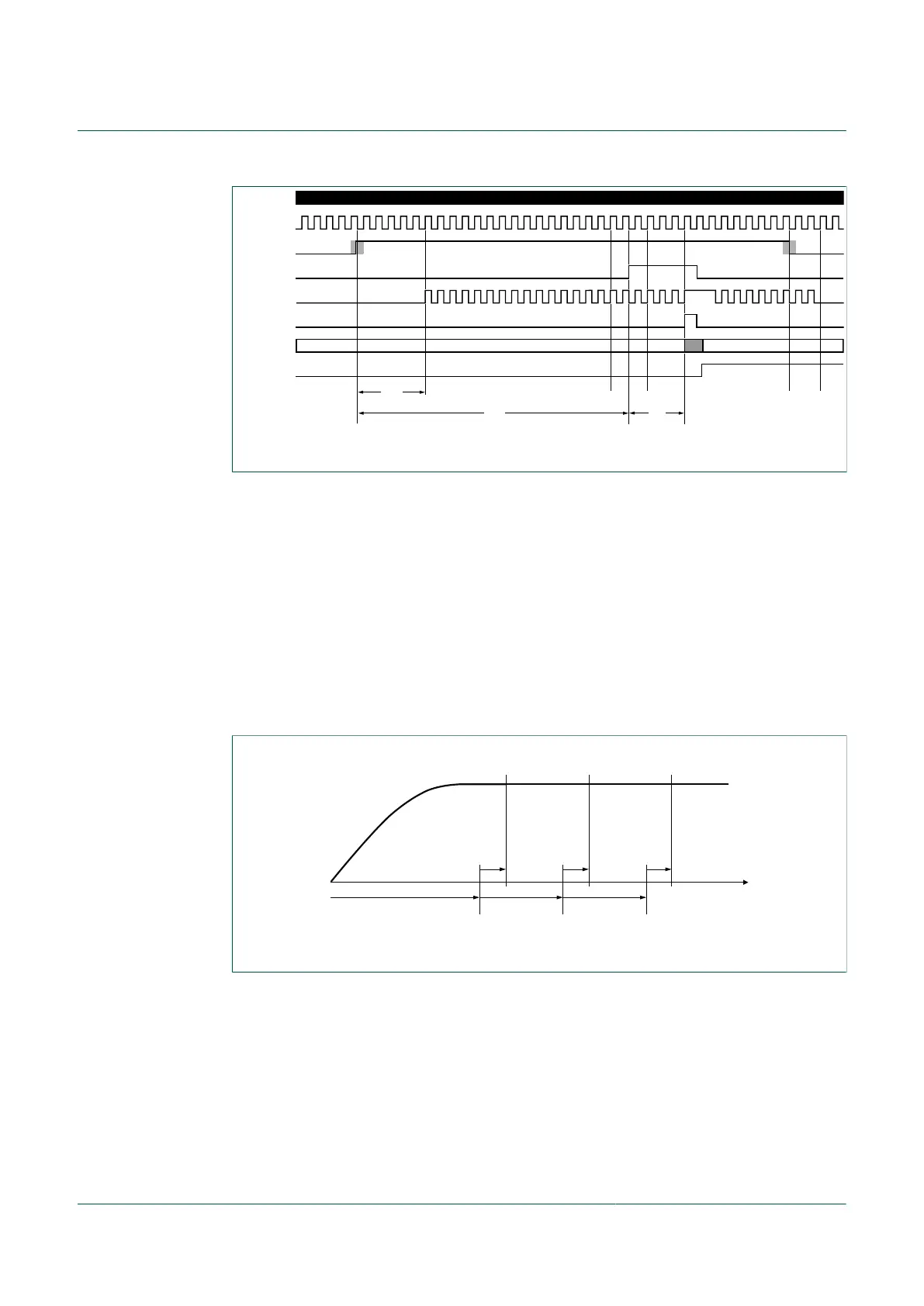
Figure 46. Direct measurement protocol
10.19.1.3 SMI low power direct sensor signal measurement mode
Operationally, two selections are described by the following timing diagram, which
assumes the application desires a series of repeating measurements denoted by the
end of the t
ADC
times. The first measurement is available from the ADC after the initial
settling delay plus the conversion time; i.e. after t
ISD
+ t
ADC
. Then each of the subsequent
measurements become available from the ADC after each t
SP
period. The period marked
by the term t
ADC
includes ~15 µs for the ADC to convert, plus ~4 us to wake up, plus
~33 µs for the ADC tasks to finish. The t
ADC
periods run concurrently with each t
SP
. The
subsequent sample periods start after the prior sample period ADC cycle has finished.
Firmware that controls the SMI and ADC must collect the result value from the ADCRES
H/L registers and store in either a parameter register or a RAM location. These tasks
must be completed before the next t
SP
begins.
aaa-031065
measurements
2nd1st 3rd, etc.
t
t
ISD
t
SP
t
ADC
t
ADC
t
ADC
t
SP
Figure 47. Initial and subsequent settling time protocol
Also, notice that t
ISD
is depicted as a rising signal level which reaches a steady state. The
SMI is designed such that the shortest t
ISD
selections will commence the measurement
process prior to the signal reaching the steady state. This is provided to allow users
the option of very high sampling rates, where absolute signal accuracy is typically not
required; i.e. the user application is more concerned with quickly checking relative rate
of change, and can tolerate reduced absolute accuracy. Typical use cases could be
checking for accelerometer changes, and not executing the compensation firmware to
save power.

 Loading...