NXP Semiconductors
UM11227
NTM88 family of tire pressure monitor sensors
UM11227 All information provided in this document is subject to legal disclaimers. © NXP B.V. 2020. All rights reserved.
User manual Rev. 6 — 24 April 2020
142 / 205
ADC trigger, then a timer such as FRC, PWU, or RTI has to be set to generate the wake
up, followed by the ADC trigger in the run mode. The ADC will subsequently generate
the COCO signal and, if enabled, its associated interrupt. Note in all cases, the ADC
COCO bit will be cleared upon the ADC interrupt service routine reading the ADCRES
Low register.
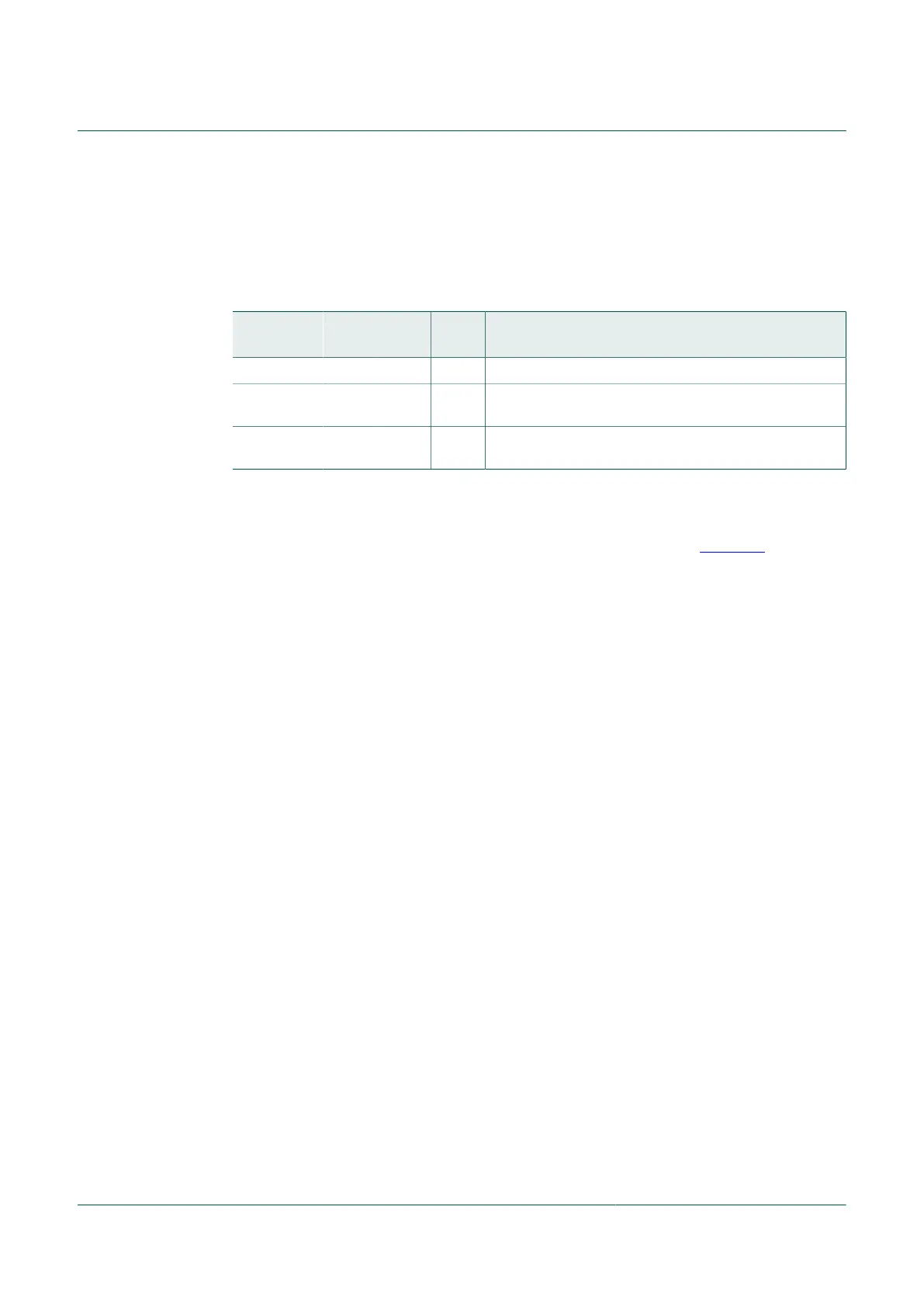
Table 145. Signal measurement sub-modes
SMI
Sub-mode
MCU
RUN
MCU
STOP4
MCU
STOP1
Comments
Automatic Yes Yes No SMI terminated after a single measurement.
Direct Yes No No SMI signal chain runs continuously, measurements are
triggered by the MCU. Stop4 entry not recommended.
LPD Yes Yes No SMI signal chain runs continuously, measurements are
repeatedly triggered automatically by the hardware.
10.19.1.1 SMI automatic signal measurement mode
In the automatic mode of operation the sensor signal measurement is triggered by setting
the SEN bit (SMICS[4]) which generates a series of signals given in Figure 45.
The typical sensor measurement software sequence would be to first select the SMI
ADC multiplexer channel, select the SMI transducer channel, filter, and Initial Settling
Delay, then set the SEN bit, then poll the SEN bit to be sure it is set, and then go into the
STOP4 mode.
When the measurement is initialized and the sample delay is completed, the ADC
Trigger signal is generated. When ADC finishes a conversion, the ADC_COCO interrupt
will wake up the MCU, and the converted result will be available at the ADCRES H/L
registers. After the ADC conversion, the SEN bit (SMICS[4]) will be cleared, which in turn
powers down the transducer (g-cell or p-cell), and the software can then use the resulting
ADC data as desired. As mentioned, this must be completed within the period noted as
t
FIN
. Once the t
FIN
has completed, the software may then initiate a new measurement
cycle by setting the SEN bit, polling the SEN bit to be sure it is set, then entering the
STOP4 mode.
Notice in this configuration that the SEN bit will be automatically cleared by the
internal signal SFO being low or cleared. Then the internal signal CLR_SEN_SYNC
signifies that the SEN signal may be written for the next measurement cycle. Since
the CLR_SEN_SYNC signal is not available for the software to access, the software
has to poll the SEN bit until it is clear, then wait for a sufficient delay time for the
CLR_SEN_SYNC to clear. Since the ADC interrupt service routine will be short, the delay
while the SEN bit is clear is recommended to be the sum of the periods t
S4WU
+ t
FIN
.
Please review the corresponding data sheet for the periods noted as t
INIT
, t
MEAS
, T
ADC
,
t
S4WU
, and t
FIN.
In this configuration, the SMIF bit (SMICS[7]) is not available.

 Loading...