NXP Semiconductors
UM11227
NTM88 family of tire pressure monitor sensors
UM11227 All information provided in this document is subject to legal disclaimers. © NXP B.V. 2020. All rights reserved.
User manual Rev. 6 — 24 April 2020
80 / 205
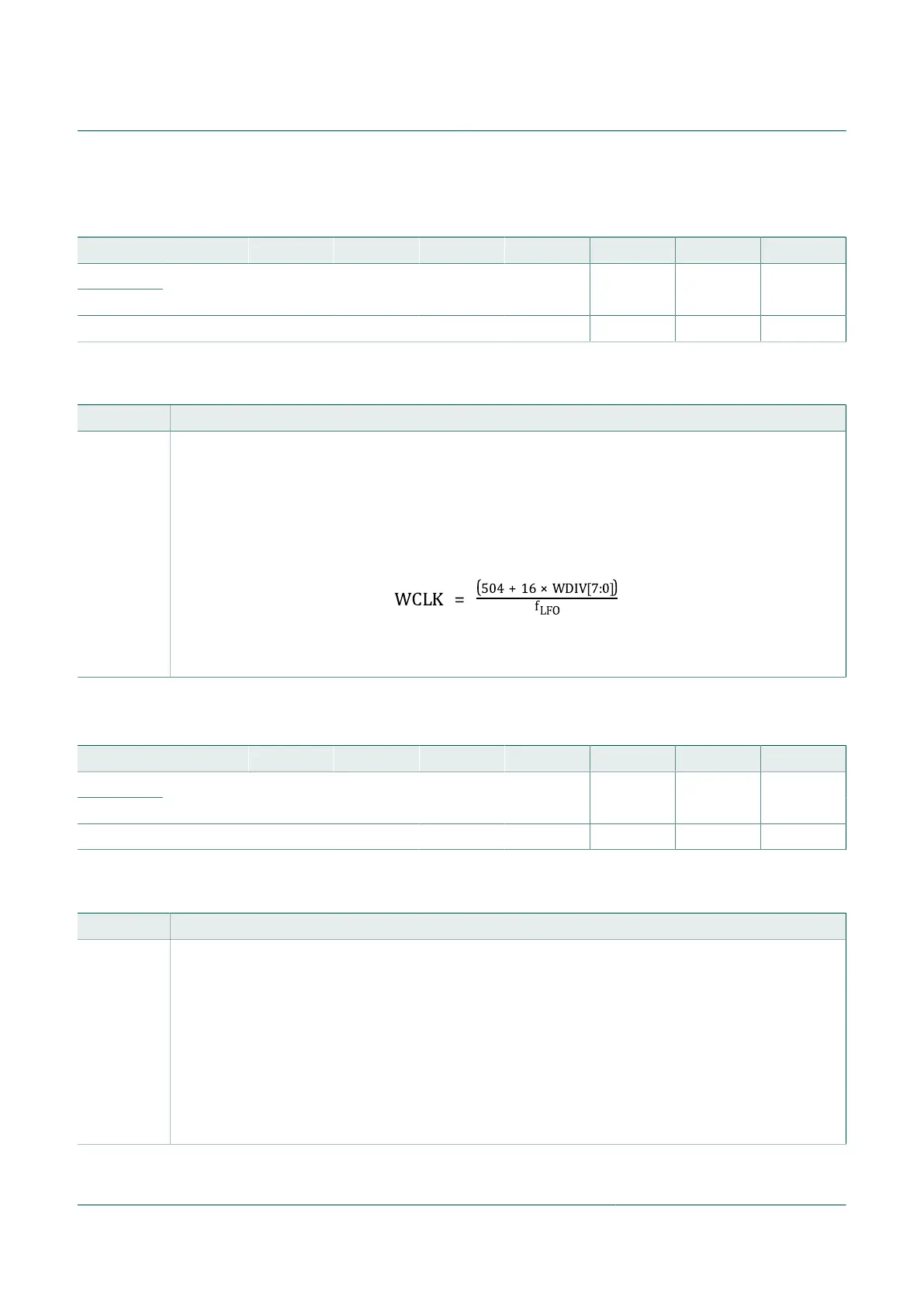
10.14.1.2 Periodic wake-up divider register (PWUDIV)
Table 64. Periodic wake-up divider register (PWUDIV) (address $001C)
Bit 7 6 5 4 3 2 1 0
R
W
WDIV7 WDIV6 WDIV5 WDIV4 WDIV3 WDIV2 WDIV1 WDIV0
Reset ($1F) 0 0 0 1 1 1 1 1
Table 65. PWUDIV register field descriptions
Field Description
[7:0]
WDIV
The WDIV[7:0] bits select a divider for the incoming LFO clock to generate the wake-up clock. The operating
range of WDIV[7:0] is $00 up to $FF. Reading WDIV[7:0] provides the value written. This results in a wake-
up clock with periods from 0.504 seconds up to 4.584 seconds, when the LFO is 1 kHz. The user can use
this divider to fine-tune the wake-up time based on the variation in the LFO frequency.
The conversion from the decimal value of the WDIV[7:0] bits to the wake-up clock time is given as described
in the following equation. Power-on-reset forces WDIV[7:0] to a value of $1F (decimal 31), and results in
WCLK of 1 second, assuming LFO is typical 1 kHz.
Where:
f
LFO
= LFO frequency in Hz, ~1 kHz typical
10.14.1.3 Periodic wake-up interrupt register (PWUCS0)
Table 66. Periodic wake-up interrupt register (PWUCS0) (address $001D)
Bit 7 6 5 4 3 2 1 0
R
W
WUT7 WUT6 WUT5 WUT4 WUT3 WUT2 WUT1 WUT0
Reset ($FF) 1 1 1 1 1 1 1 1
Table 67. PWUCS0 register field descriptions
Field Description
[7:0]
WUT
The WUT[7:0] bits select the number of wake-up clocks until the next wake-up interrupt is generated.
Wake-up interrupt time RCLK = Wake-up clock time WCLK x WUT[7:0]
The WUT[7:0] gives a range of wake-up interrupt times from 1 to 255 x wake-up clocks. Depending on the
value of the bits for the WDIV[7:0] this time interval can nominally be from 0.504 s to 1168.92 s in 0.504 s
steps.
Whenever the WUT[7:0] bits are changed, the timeout period is restarted. Writing the same data to the
WUT[7:0] bits has no effect. Writing zeros to all of the WUT[7:0] bits forces the wake-up divider to a value
of $FF and disables the wake-up interrupt. However, writing all zeros to the WUT[7:0] bits is inhibited if all
of the PRST[7:0] bits are already cleared to zero. This prevents disabling both the periodic wake-up and the
periodic reset at the same time. The WUT[7:0] bits are preset to a value of $FF (decimal 255) by any resets.
$FF = Result of power on or periodic wake-up unit reset.

 Loading...