NXP Semiconductors
UM11227
NTM88 family of tire pressure monitor sensors
UM11227 All information provided in this document is subject to legal disclaimers. © NXP B.V. 2020. All rights reserved.
User manual Rev. 6 — 24 April 2020
91 / 205
instructions in the application program. Additional bytes are received until a bit time that
is not Manchester encoded is found. If a non-Manchester bit time is found, the LFERF bit
will be set and indicates a Manchester coding error. If this happens on the first bit of the
next byte of the message the LFEOMF bit will also be set.
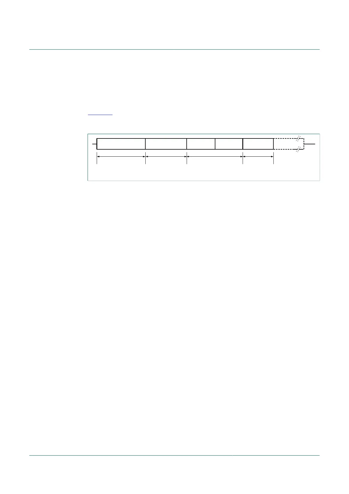
The preamble is a period of Manchester bits before the SYNC pattern as shown in
Figure 28. The SYNC pattern will only be matched for the bit times specified by the
SYNC[1:0] control bits. Depending on the expected SYNC pattern the allowed preambles
is as described for the SYNC[1:0] bits in the LFCTL3 register.
aaa-028028
PREAMBLE SYNC HIGH ID DATA DATA
6, 7.5 or 9 T
0, 8 T or 16 T
IDSEL[1:0]
8 T
t
LFPRE
Repeat for 0-n bytes
LOW ID
Figure 28. Telegram format (carrier preamble)
10.15.14 Error detection and handling
When the DECEN bit is set, LFR messages are monitored for data rate or SYNC errors,
incorrect message ID, and Manchester coding errors. When an error is detected the LFR
goes back to sniff mode until the end of ON time completion, if ONMODE is set; or turns
off until the start of the next scheduled sampling interval, if ONMODE is cleared. Because
the MCU uses more power than the LFR module, it is desirable to keep the MCU in low
power standby modes as much as possible. Therefore, the handling of these errors will
be performed by the LFR and not require additional software processing by the MCU.
When the DECEN bit is clear, there is no monitoring on data. The MCU needs to poll
the state of the LFDO bit and create its own decoding scheme within software on the
detected signal. To be able to start the polling only when data are received, the carrier
detection flag is enabled in data mode when DECEN = 0. During data reception, the
auto-zero sequence is performed at each LFO period. The MCU needs also to determine
the end of the telegram and turn off the LFR (LFEN = 0) during two LFO cycles before
any other operations.
10.15.15 Continuous ON mode
In the Continuously ON mode, the LFR module will remain on continuously while the
LFEN bit is set. The Continuously ON mode is controlled by setting the LFSTM[3:0] bits.
In the Continuously ON mode, if a signal is successfully processed by the digital, the LFR
module will stop and restart automatically. The gap is 2-3 LFO periods. Also if TOGMOD
bit is set, the LFR module will stop after the ON time cycle and re- start automatically,
after having changed the CARMOD bit.
10.15.16 Initialization information
When power is applied to the MCU, the LFR must be initialized and configured before it
can begin to receive LF messages. Several systems in the LFR require factory trimming
to ensure operation within specified limits. After these trim values are written, they remain
constant until the next MCU reset.
The application program must set up control bits and registers to configure the LFR to
determine the structure of the message telegram, the input sensitivity, and other LFR

 Loading...