NXP Semiconductors
UM11227
NTM88 family of tire pressure monitor sensors
UM11227 All information provided in this document is subject to legal disclaimers. © NXP B.V. 2020. All rights reserved.
User manual Rev. 6 — 24 April 2020
90 / 205
checks for a carrier. In the carrier detect mode, as soon as a carrier is detected, the
LFCDF flag is set. If LFCDIE is also set, an interrupt request is sent to wake the MCU
The format of the complete Manchester encoded datagram is comprised of a Manchester
data preamble (series of Manchester 1s or 0s), a synchronization period, an optional ID,
and zero to n data bytes.
The synchronization period can be used for synchronizing the beginning of the data
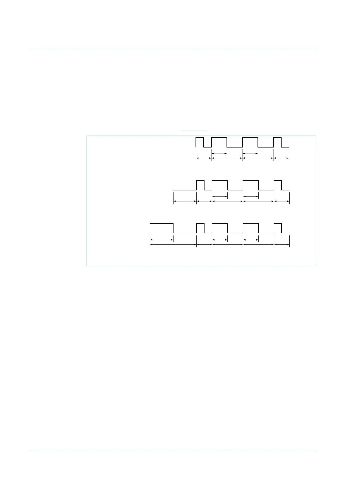
packet. The SYNC pattern that follows the preamble can be either a 6-, 7.5- or 9 bit-time
non-Manchester pattern as shown in Figure 27.
aaa-028027
6-bit
(6 T)
pattern
SYNC[1:0] = 01
7.5-bit
(7.5 T)
pattern
SYNC[1:0] = 10
9-bit
(9 T)
pattern
SYNC[1:0] = 11
T
T T
T
2 T 2 T
T1.5 T
T T
T2 T 2 T
T3 T
1.5 T T T
T2 T 2 T
Figure 27. SYNC patterns
These patterns would normally not appear anywhere in the Manchester encoded portion
of a message so there is no possibility that the LFR could accidentally synchronize
to a message that was already in progress when the LFR started listening for a
message. These patterns are also complex enough so that it is very unlikely that noise
or interference could be mistaken for these SYNC patterns. In the data mode and after
the detection of a valid carrier, the LFR will decode the data stream waiting for the SYNC
word. Should this carrier not be an accepted TPMS type, no SYNC will be received and
the LFR module will stay in data receive mode forever. A timeout counter is therefore
started after a carrier detection and will stop the receiver if reaching the programmed
value selected by the TIMOUT[1:0] bits in the LFCTL4 register. This timeout counter is
clocked by the internal LFRO clock.
The LFR can be configured to have an optional 0, 8-bit, or 16-bit ID after the SYNC
pattern. If the ID value matches the received ID, the message is accepted. The ID value
can be used to identify a specific receiver, a message type, or some other identifier as
defined by application software.
Any number of data bytes can be included after the ID. The LFR begins to assemble
data bytes from the incoming signal as soon as the ID check is complete. If the first bit-
time after the last bit of the ID does not conform to Manchester coding requirements,
the LFR considers the message complete and terminates the LFR operation without
setting the data ready flag (LFDRF). If data follows the ID, it is serially received and when
8 bits have been received the LFR copies this byte into the LFDATA register and sets
the LFDRF flag. If the LFDRIE interrupt enable is also set (and it should be), an interrupt
request is sent to wake the MCU so it can read the data and process it according to the

 Loading...