NXP Semiconductors
UM11227
NTM88 family of tire pressure monitor sensors
UM11227 All information provided in this document is subject to legal disclaimers. © NXP B.V. 2020. All rights reserved.
User manual Rev. 6 — 24 April 2020
145 / 205
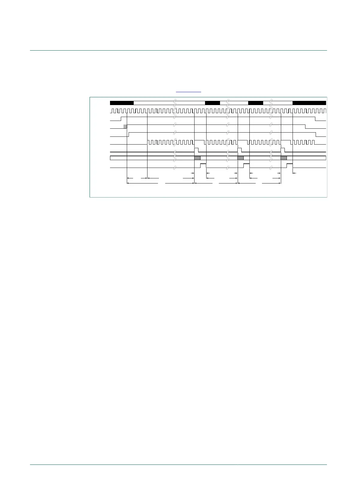
In the low power direct mode of operation, the sensor signal measurement is automated
after the user software manages the SMICS[3] (LPDM), SMIC[7] (SMIEN) and SMIC[6]
(SCAP) control bits as shown in Figure 48.
aaa- 035954
STOP4
3 cyc
t
INIT
3 cyc 3 cyc
N
SP
cyclesN
SP
cyclesN
ISD
MFO cycles
t
ISD
t
SP
t
SP
STOP4 STOP4RUNRUN RUN RUN
MCU Activity
MFO
LPDM
SMIEN
SCAP
SFO
ADC Trigger
ADC Activity
IDLE IDLE IDLE IDLE
ADC COCO
Figure 48. Low power direct measurement protocol
The typical sensor measurement software sequence would be to first select the SMI
ADC multiplexer channel, select the SMI transducer channel, and filter. Then execute
the sequence to enter LPDM as described below. In this mode, due to the MCU entering
STOP4 mode between measurements, the initial and subsequent delays are also to be
configured and used by the system. The software application then sets the SMIEN bit,
and then sets the SCAP bit. The SMI will then use the SCAP bit being set to synchronize,
such that after the period t
ISD
(on the 1st measurement) the ADC Trigger will be set.
The SCAP bit will be cleared by the software application exiting LPDM mode. The ADC
will then complete the conversion and the ADC COCO interrupt will be asserted. The
ADC COCO signal is cleared when the software reads the results from the ADCRES H/L
registers.
At this point, the application may choose to stop measurements by clearing the SMIEN
bit and exiting the LPDM mode. LPDM mode is exited by clearing the SMIEN and the
LPDM bits on two consecutive write operations performed immediately after the MCU
wakes from STOP4. The SCAP bit will automatically clear after the LPDM bit goes low.
Notice the second and subsequent settling periods t
SP
begin at the prior measurement
ADC Trigger bit being set. The process will continue until the software application clears
the SMIEN bit and exits the LPDM mode.
Note that if the software application will change any settings within the SMI, such as
the transducer channel or filter, then the application should again use the longer ISD to
assure the signal is allowed to settle. Each new entry into LPDM will cause the ISD delay
to be employed on the first measurement, followed in subsequent measurements by the
SP delay.
Please review the corresponding data sheet for the periods noted as t
ISD
and t
SP.
The LPDM bit will allow the system to acquire data as on the Direct Mode, but the MCU
can go to STOP4, since the hardware will control the acquisition time. The sequence to
get in this mode is important and must be three consecutive writes on the bits SMICS[3]
(LPDM), SMIC[7] (SMIEN), and SMIC[6] (SCAP), then the user software can enter
STOP4.
1. Set LPDM bit to 1, then
2. Set SMIEN bit to 1, then
3. Set SCAP bit to 1, then Enter STOP4 mode.

 Loading...