4-30
Chapter 4 I/O SETTINGS
ZW
User’s Manual
Chapter 4
Settings for I/O
■ Setting the clamp value
If [Clamp] is selected for the processing when measurement cannot be performed, set
the clamp value to be output.
• For analog output
• For binary output
As an example, here is an explanation of the procedure for setting the clamp value to
"analog voltage output 10 V".
Operating procedure
Output Setting
When current is
output
MIN (approximately 3.4 mA)/ 4 to 20mA (every 1 mA)/ MAX (approximately 21
mA), (Default value: MAX)
When voltage is
output
MIN (approximately -10.8 v)/ -10 to 10 V (every 1 V)/ MAX (approximately 10.8
V), (Default value: MAX)
Setting
MIN (-1048576)
MAX (1048575) (Default value)
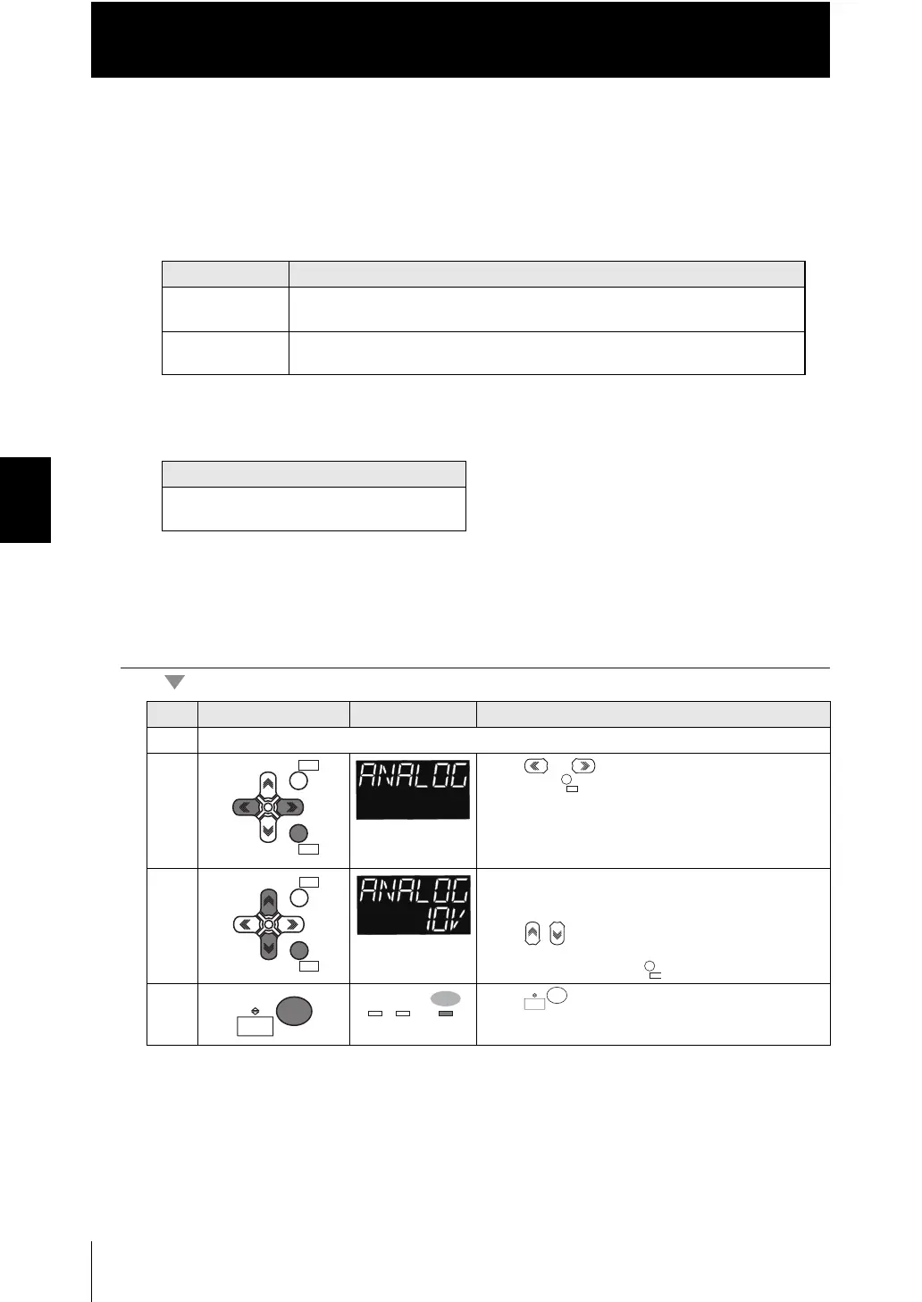
Steps
Key operation Display Description
1 - 4 For moving to HLD.RST - CLAMP, see steps 1 to 4 in p.4-29
5 Press or keys to select either of "ANALOG"
and press key.
6 Set the clamp value.
The current setting value is displayed on the sub-
display.
Press / keys to enter the editing mode, and the
sub-display blinks.
Select "10V" and press key.
7 Press key for two seconds to enter the RUN
mode.
ZERORST/
ESC
ZERO/
SET
ZERORST/ZERORST/
ESCESC
ZERO/ZERO/
SETSET
RUN
FUN
TEACH
 Loading...


