4-34
Chapter 4 I/O SETTINGS
ZW
User’s Manual
Chapter 4
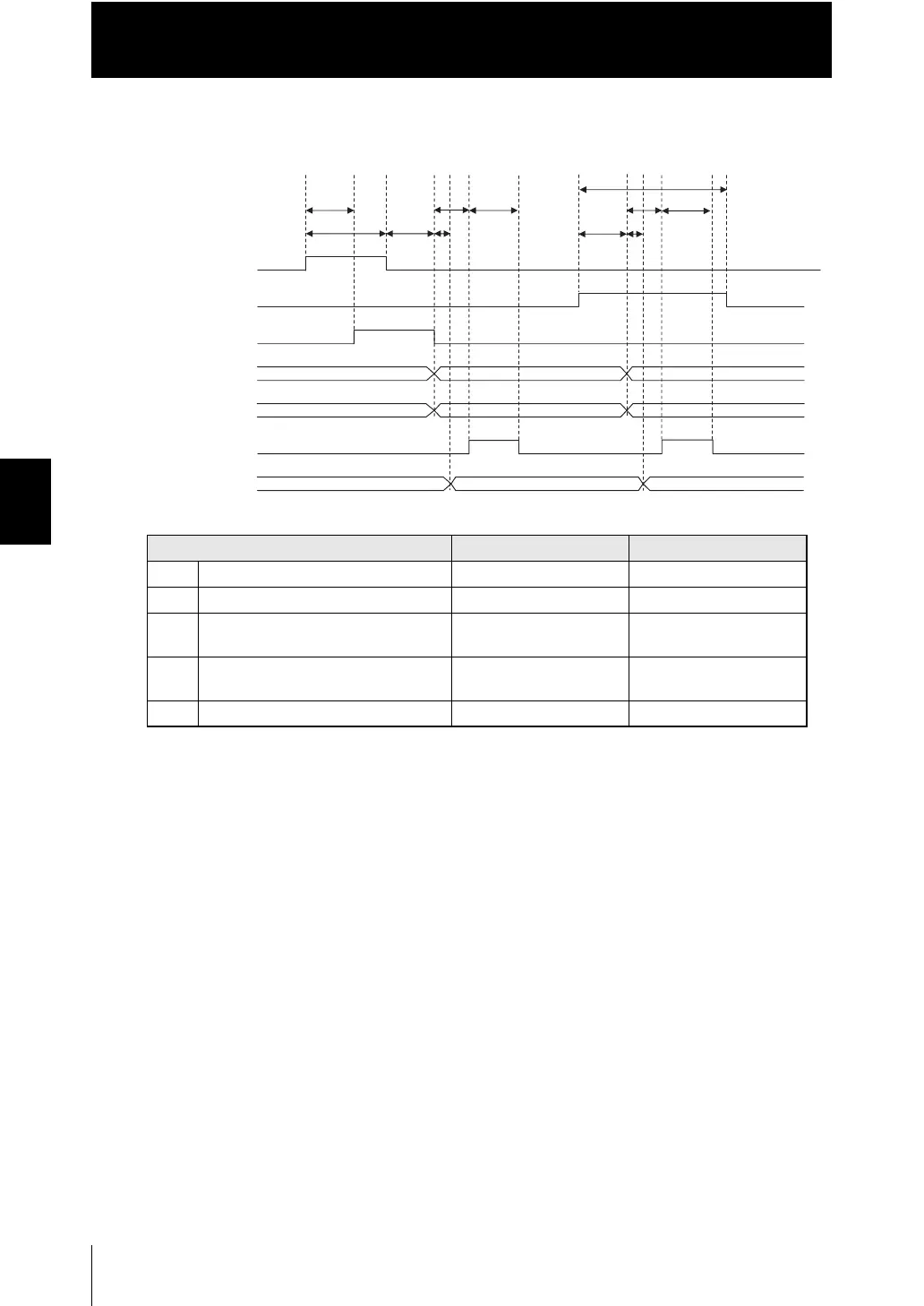
Timing Charts
■ Peak/Bottom/Peak to peak/Average hold
●
Explanation of operations
(1) The trigger signal is turned ON.
(2) During the trigger input minimum time, when the trigger is input is ON, sampling
is started and the BUSY signal is turned ON.
(3) After the end of measurement, the judgment results and binary data are output.
(4) After the trigger signal goes OFF, sampling is ended and the judgment results
and binary data are output. The BUSY signal is also turned OFF.
(5) After the judgment result and binary data output, the analog output is updated.
(6) After the judgment result and binary data output, the GATE signal is turned ON.
(7) The GATE output time after the GATE signal is turned ON, the GATE signal is
turned OFF.
(8) The reset signal is turned ON. During the reset input minimum time, if the reset
signal is turned ON, the measured value is reset.
(9) The judgment results and binary data are reset.
(10) After the judgment results and binary data are reset, the analog output is reset.
(11) After the judgment results and binary data are reset, the GATE signal is turned
ON.
(12) The GATE output time after the GATE signal is turned ON, the GATE signal is
turned OFF.
(13) The reset signal is turned OFF.
Item Minimum Maximum
T3 Response time of analog output - 0.1 ms
T4 GATE signal rise time - 0.2 ms
T5 Output time of GATE signal Setting value
(0.1 to 100.0 ms)
Setting value
(0.1 to 100.0 ms)
T6 Trigger input/reset input minimum
time‘
3 ms+T0 -
T7 Response time of input 2 ms+T0 3 ms+T02
(2) (3)
T6
(4) (5)
T7
T6
T3
T4
(6)
T5
(7) (8)
T7
(9)
(10)
T7
(11)
(1)
ON
OFF
ON
OFF
ON
OFF
ON
OFF
T3
T4
T5
(12) (13)
Judgment output
(HIGH/PASS/LOW)
Binary output
GATE output
Analog output
Busy output
Reset output
(RESET)
Trigger output
(TIMING)
 Loading...


