Chapter 1 MEASUREMENT SETUP
Chapter 1
Part Names and Functions
1-5
ZW
User’s Manual
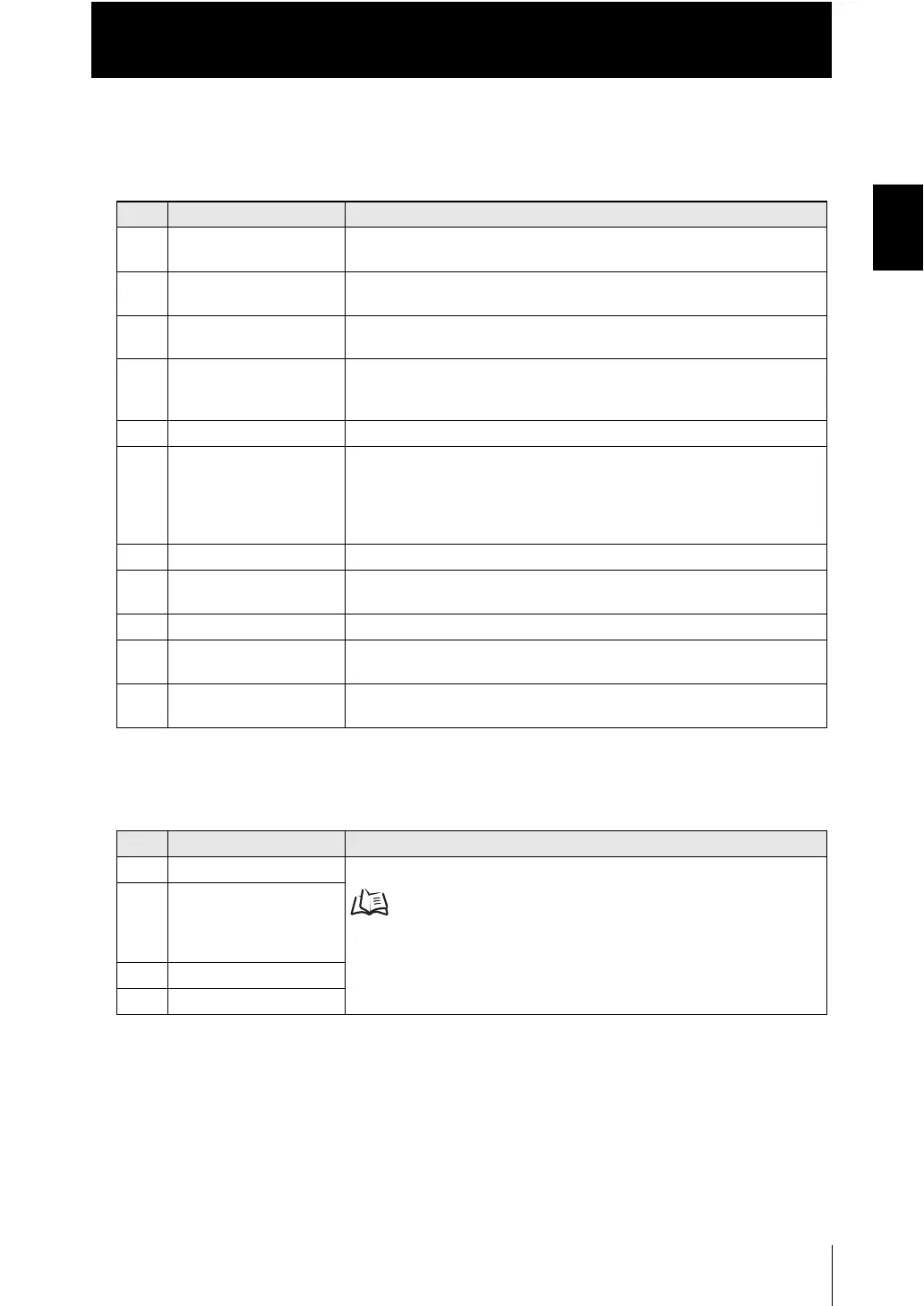
■ Front view
● Display
● Control panel
No. Names (light color) Functions
1 HIGH indicator (orange) The HIGH indicator is lit while judgment is resulted in HIGH (HIGH
threshold value measured value).
2 PASS indicator (green) The PASS indicator is lit while judgment is resulted in PASS (LOW
threshold value measured value HIGH threshold value).
3 LOW indicator (orange) The LOW indicator is lit while judgment is resulted in LOW (measured
value LOW threshold value).
4 STABILITY indicator
(green)
The STABILITY indicator is lit while a measured value is within the
measuring range.
It goes out if a measured value is out of the measuring range.
5 ZERO indicator (green) The Zero Reset indicator is lit while the zero reset function is enabled.
6 ENABLE indicator (green) The ENABLE indicator lights when the Sensor is ready for measurement. It
goes off when measurement is not possible (e.g. when the received light
amount is excessive or insufficient, when the measuring range is
exceeded, when the calibration ROM is not connected, or when
measurement is not being performed in FUN mode).
7 Main display (red) The main display shows measured values and/or function names.
8 Sub-display (green) The sub-display shows additional information for measured values or
setting values for functions.
9 RUN indicator (green) The RUN indicator is lit in the RUN mode, and goes out in the FUN mode.
10 THRESHOLD-L indicator
(orange)
The LOW threshold value indicator is lit when the Sub-display indicates a
LOW threshold value.
11 THRESHOLD-H indicator
(orange)
The HIGH threshold value indicator is lit when the Sub-display indicates a
HIGH threshold value.
No. Names Functions
12 ZERORST/ESC key These keys function differently depending on operation modes.
Functions of Operating Keys p.2-3
13 (LEFT) key
(RIGHT) key
(UP) key
(DOWN) key
14 ZERO/SET key
15 Mode switching key

 Loading...


