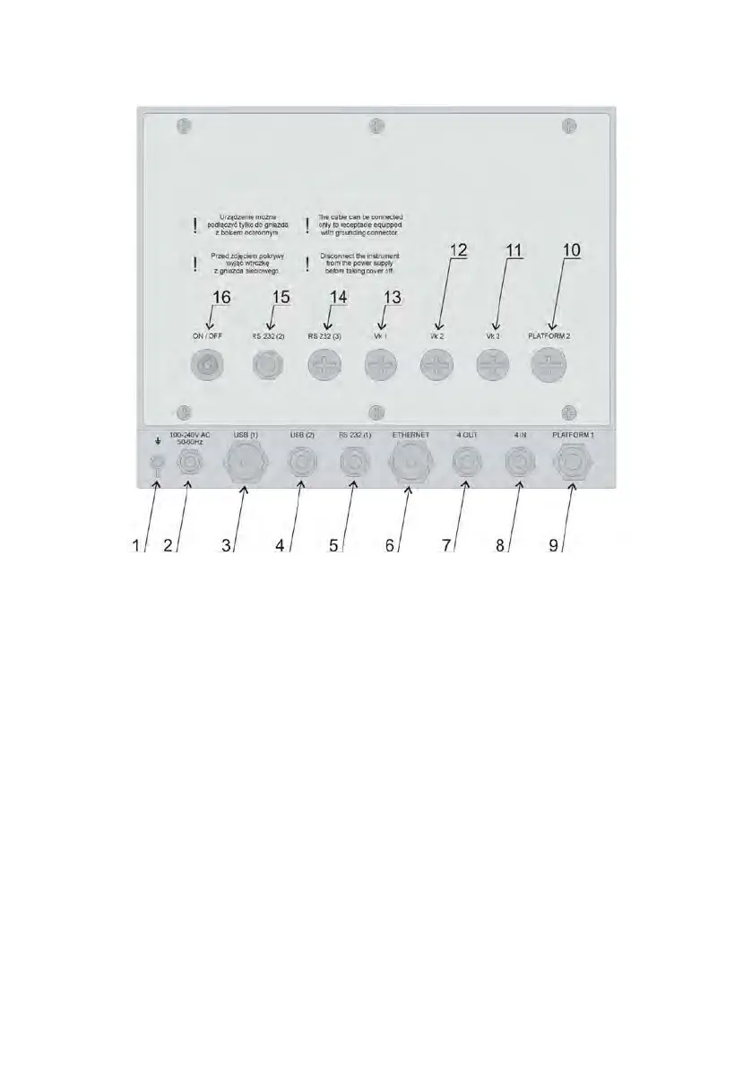
5.3. Description of connectors
Sockets in PUE HY10
1. Ground connector.
2. Power cord gland.
3. USB A connector.
4. USB M12 4P connector.
5. RS232(1) M12 8P connector.
6. Ethernet RJ45 connector.
7. 4WY M12 8P connector.
8. 4WE M12 8P connector.
9. Gland for platform 1.
10. Gland for platform 2.
11. Socket for optional cable gland/additional equipment connector (Vk3, 12IN,
PROFIBUS IN) – indicator type dependent mounting, plugged by default.
12. Socket for optional cable gland/additional equipment connector
(Vk2, 12OUT, PROFIBUS OUT) – indicator type dependent mounting, plugged by
default.
13. Socket for optional cable gland/additional equipment connector (Vk1, RS485,
Analog OUT) – indicator type dependent mounting, plugged by default.
14. RS232(3) M12 8P optional connector.
15. RS232 (2) connector.
16. ON/OFF switch.

 Loading...