EasyManua.ls Logo

RADWAG PUE HY10

RADWAG PUE HY10
305 pages
To Next Page IconTo Next Page
To Previous Page IconTo Previous Page
Loading...
249
40.1.3. Inputs/Outputs signals overview
Signals transferred via 16x0.5mm
2
cable with numbered wires.
INPUTS OUTPUTS
WIRE NUMBER SIGNAL WIRE NUMBER SIGNAL
1
IN1
1
OUT1
2
IN2
2
OUT2
3
IN3
3
OUT3
4
IN4
4
OUT4
5
COMM1
5
COMM1
6
IN5
6
OUT5
7
IN6
7
OUT6
8
IN7
8
OUT7
9
IN8
9
OUT8
10
IN9
10
OUT9
11
COMM2
11
COMM2
12
IN10
12
OUT10
13
IN11
13
OUT11
14
IN12
14
OUT12
15
COMM3
15
COMM3
40.2. 4IN/4OUT 4IN
Signals are transmitted via cables fed through cable glands.
40.2.1. 4IN/4OUT module: technical specifications
Output parameters
Outputs number 4
Outputs types Solid-state relay
Wire cross-section 0,14 - 0,5mm
2
Maximum switching current 0,5A DC
Maximum forward voltage 30VDC, AC
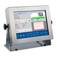
Table of Contents

Other manuals for RADWAG PUE HY10

Related product manuals