Build 21 v21.4.1
© 2007-2010 RED.COM INC. FEBRUARY 23, 2010
112 112
VIEWFINDER (RED EVF) INTERFACE
The RED EVF interface is a custom digital video and power interconnection between the camera and a
RED EVF. Due to the requirement for absolute data integrity that requires custom cable construction, the
pin-out of this interface is not published.
Contact RED technical support for available RED EVF cable lengths.
MONITOR (RED LCD) INTERFACE
The RED LCD interface is a custom digital video and power interconnection between the camera and a
RED LCD. Due to the requirement for absolute data integrity that requires custom cable construction, the
pin-out of this interface is not published.
Contact RED technical support for available RED LCD cable lengths.
NOTE: The Aux/RS232, RED EVF and RED LCD connectors use the same shell size. Do not attempt
to force fit a 10-pin Aux/RS232 cables into a 16-pin RED EVF or RED LCD connector, or force fit a
16-pin RED EVF or RED LCD cable into a 10-pin Aux/RS232 connector.
LINE LEVEL / MICROPHONE LEVEL AUDIO INPUTS
A three-pin mini-XLR connector is provided for each of the camera’s Line / Microphone inputs. Audio is
recorded at 24-bit 48KHz, which provides high audio fidelity and wide dynamic range. The Line Level and
Microphone Level analog audio input signals are routed via a high quality A/D and pre-amplifier, whose
gain stage may be controlled using the Input Level control to achieve the desired audio reference / re-
cording level.
To assist with audio operating reference level setup, the camera provides a color-coded Peak Level meter
with 0dBu (-20dbFS) Witness Mark in the Graphical User Interface.
Peak Level meter range is –34dBu to +20dBu (-54dBFS to 0dBFS) and provides clip indication.
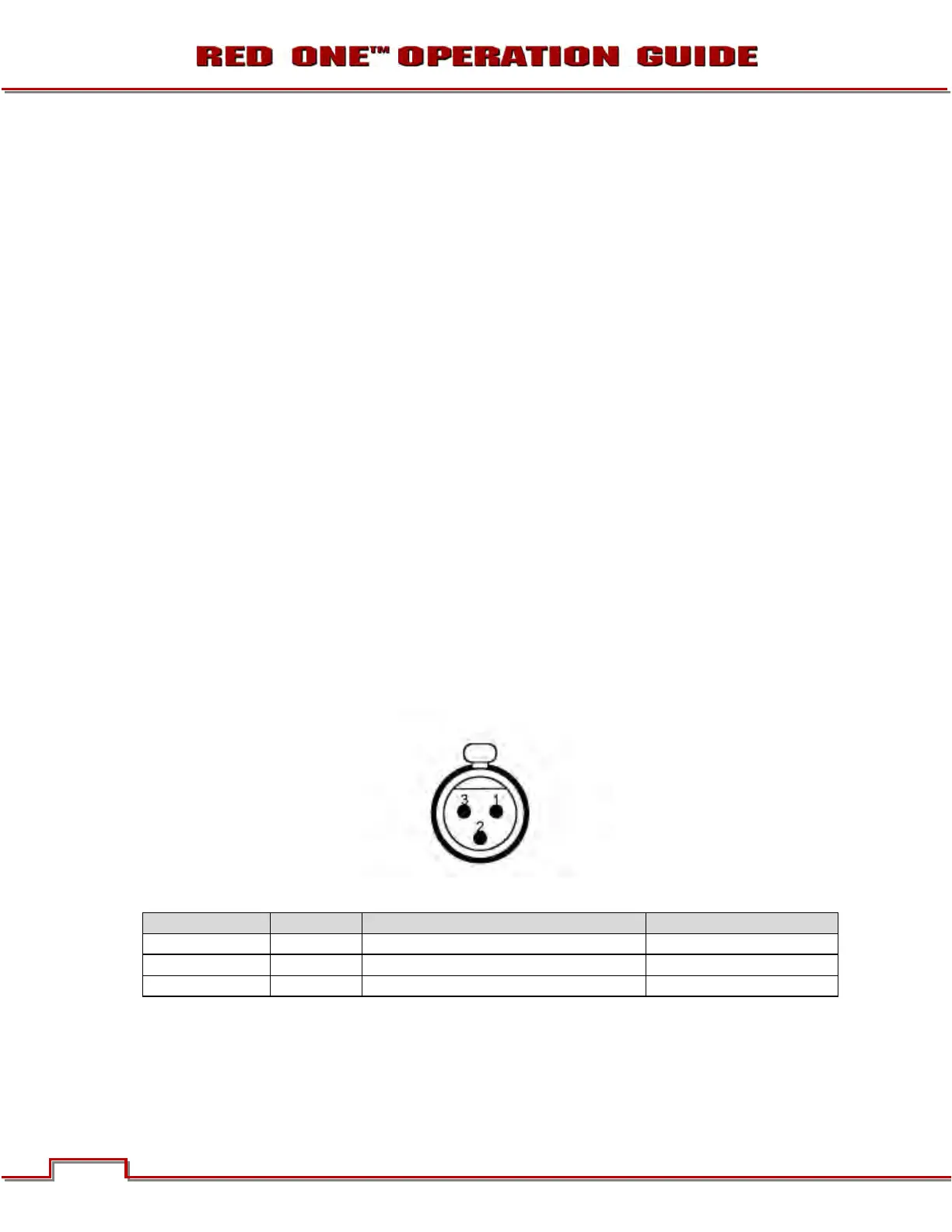
Microphone / Line Audio Input Signals (3-pin mini-XLR) Connector
Pin: Signal Description Direction
1
GROUND Camera ground --
2
IN+ Mic/Line input (+48V phantom power) In
3
IN- Mic/Line input (+48V phantom power) In
Line Level Audio Inputs
Line Level audio inputs are designed to operate at unity gain (0dB Input Level); therefore an appropriate
line output level should be established by your production mixer or other signal source.