Build 21 v21.4.1
FEBRUARY 23, 2010 © 2007-2010 RED.COM INC.
13
NOTE: Cameras shipped prior to Sept 15th 2008, may have an earlier revision of the audio board
and no S4/i pins installed in the P/L mount. Contact RED customer service about appropriate audio
cables to use with these systems, and hardware upgrade options.
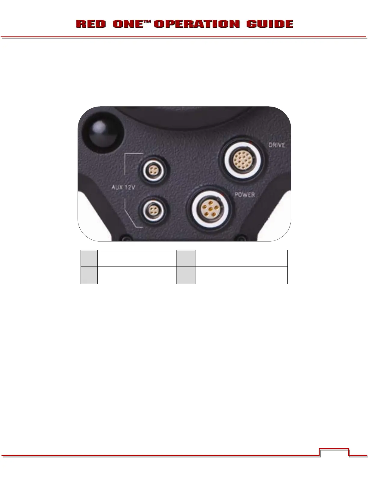
REAR OF CAMERA
A
Aux Power / GPIO A
C
Camera Power 11.5 – 17V DC Input
B
Aux Power / GPIO B
D
e-SATA Interface (to RED-DRIVE or
RED-RAM digital magazine)
Figure 6 – Lower Rear Camera Connectors
On the rear of the camera are the two 4-pin Auxiliary Power / GPIO outputs (A, B), 6-pin camera system
POWER input (C) and a 16-pin DRIVE interface (E).
Each Auxiliary Power / GPIO connector can supply 1.75 amps of unregulated 11.5 – 17V DC to accesso-
ries such as range finders or low power lens motors. The upper connector provides a GPI trigger (user
programmable but defaulted to Record Start / Stop) and a Record Tally output. The lower connector pro-
vides a GPI trigger (user programmable but defaulted to Record Start / Stop – for Time-lapse set to TIM-
LAPSE in GPIO preferences) and a Frame Recorded Tally output.
The DRIVE interface supplies power and data over e-SATA protocols to record REDCODE (TM) RAW
compressed video data, metadata and audio to RED-DRIVE or RED-RAM digital media.
A
B
C