Build 21 v21.4.1
© 2007-2010 RED.COM INC. FEBRUARY 23, 2010
120 120
AUXILIARY POWER OUTPUTS
The camera provides two auxiliary power output connectors (C, D) on its back panel. Each output sup-
plies un-regulated +11.5 to 17V battery pass-through power between pins 1 and 4. Maximum sustained
current draw is 1.5 Amp per output. These power output pins are over-current protected, and are only ac-
tivated by the camera on boot up. If the over-current circuits trip, power cycle the camera to re-activate
the outputs.
1
4
3
2
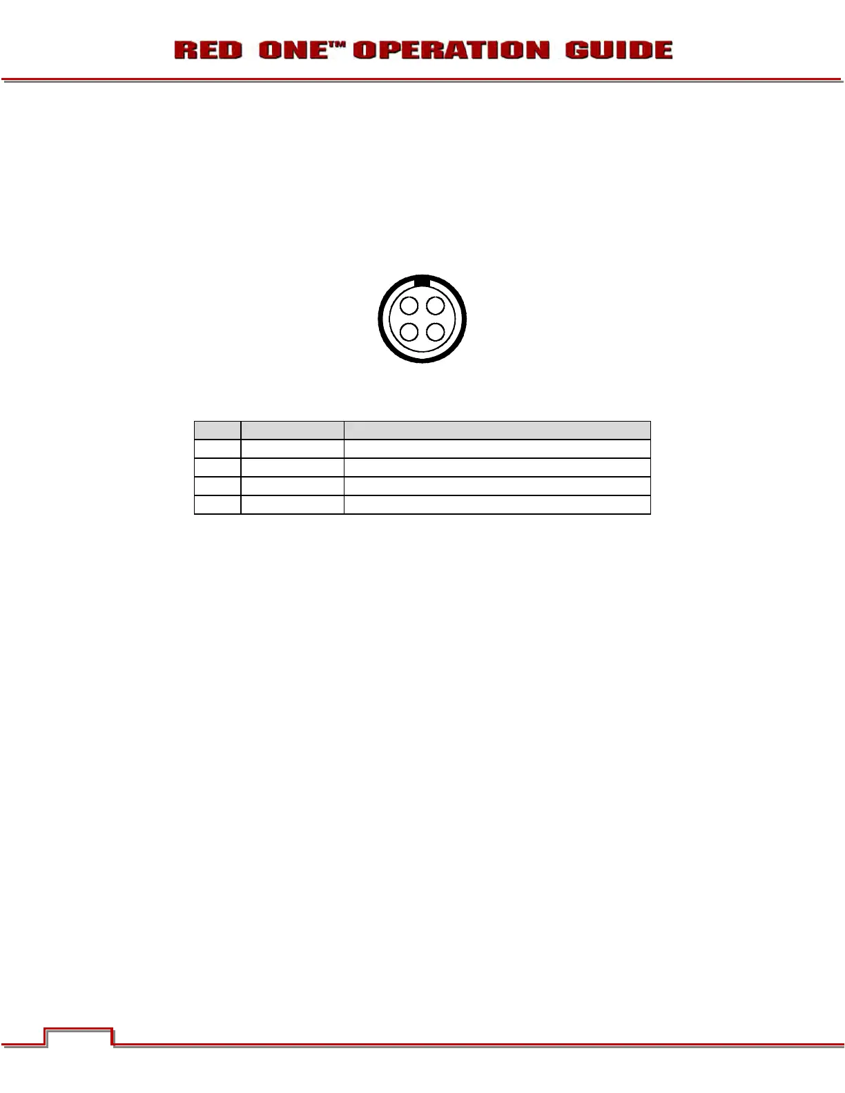
View into camera Auxiliary Power Output connector
Mating Connector: LEMO FGG.0B.304.CLAD42Z
Pin Signal Description
1
GROUND Auxiliary power return (Camera Ground)
2
GPI Input (Trigger)
3
GPO Tally
4
+VOUT Auxiliary power output
Each connector also provides a low voltage trigger input (GPI) and tally output (GPO) on pins 2 and 3,
whose functions can be configured in the GPIO preferences menu. The upper connector contains GPI A
and GPO A, the lower connector contains GPO A and GPO B. The default setting for both GPI A and B is
Record Start/Stop and for GPO A and B is Record Tally.
1. To activate a GPI trigger, momentarily short pin 2 to 1.
2. When active, the GPO tallies present 3.3 V @ 0.04 amps maximum between pins 1 and 3.
WARNING: If creating a GPI trigger cable it is very important not to short pin 4 to pin 3, as this
could cause damage to the camera’s power supply; this is not covered by Warranty.