Build 21 v21.4.1
© 2007-2010 RED.COM INC. FEBRUARY 23, 2010
12 12
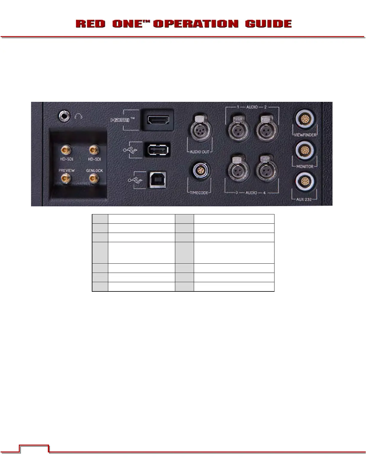
CAMERA CONNECTORS
RIGHT SIDE OF CAMERA
This section describes the physical connectors on the RED ONE camera body. For detailed description
and operation refer to APPENDIX D: INPUT/OUTPUT CONNECTORS.
A
Headphone
H
USB Slave
B
Program HD-SDI (A)
I
Audio Out
C
Program HD-SDI (B)
J
Timecode
D
Preview HD-SDI
K
Audio In Ch 1 – 4 (1-2 Upper
Left - Right, 3-4 Lower Left -
Right)
E
Video Genlock
L
Viewfinder for RED EVF
F
HDMI Out
M
Monitor for RED LCD
G
USB Master
N
Aux / RS232
Figure 5 – Right Side Camera Connections
The right side of the camera contains all the video, audio and time code inputs and outputs.
From top left to bottom right, these comprise a 3.5mm stereo headphone jack (A), and four DIN 1.0/2.3
video connectors that support Program HD-SDI (B, C), Preview HD-SDI (D) and Video Genlock (E).
Next is an HDMI output (F), a USB-2 “master” port (G) to connect the camera to another camera or to
connect a USB memory device to update camera firmware, a USB-2 “slave” port (H) to connect the cam-
era to another camera or computer based controller, a 5-pin mini-XLR audio output (I), a 5-pin timecode
input/output (J) and four (4) 3-pin mini-XLR audio inputs (K). Finally there are two 16-pin push lock LEMO
connectors (L, M) that provide video, communications and power for a RED EVF (L) and RED LCD (M),
and a 10-pin push lock LEMO connector (N) supporting the Aux/RS232 port that can interface to a variety
of B4 lenses and lens motor control devices.
One 6-inch length DIN 1.0 / 2.3 to BNC video adaptor cable and one 9-inch length 3-pin mini-XLR to mini-
XLR cable plus a mini-XLR to full size XLR adaptor are provided with the camera.
Additional video and audio adaptor cables may be ordered online at www.RED.com/store.
A
B
C
D E
F
G
H
I
J
L
M
N