Build 21 v21.4.1
FEBRUARY 23, 2010 © 2007-2010 RED.COM INC.
119
DC POWER INPUT
The POWER input connector (A) accepts a DC voltage between +11.5 and +17V DC. When used with a
RED-BRICK 140 battery, the camera also receives battery status information. The power input is pro-
tected against reverse-polarity connection, ESD, under voltage, and over current.
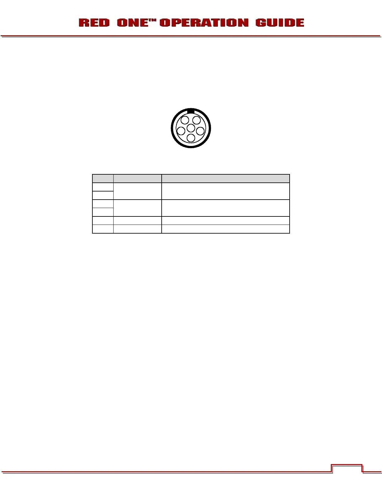
View into camera Power Input connector
Mating Connector: LEMO FGG.2B.306.CLAD62Z
Pin Signal Description
1
+VBATT Power input, +11.5 to +17VDC
2
3
GROUND Power Return (Camera Ground)
4
5
SCL_BATT Battery pack I2C bus clock
6
SDA_BATT Battery pack I2C bus bi-directional data
WARNING: It is very important that both pairs of +VBATT and GROUND pins are wired up. DO NOT
fabricate power cables with just one each of +VBATT and GROUND pins wired, as this will cause
damage to the camera’s power supply; this is not covered by Warranty.
DRIVE INTERFACE
The Drive Interface (B) is a custom e-SATA and power connection for RED-DRIVE and RED-RAM media.
Due to the requirement for absolute data integrity that requires custom cable construction, the pin-out of
this interface is not published.
Contact RED technical support for details of available drive interface cable lengths.
NOTE: The Drive Interface and D.C Power Input connectors use the same connector shell size. It is
very important you do not try to force a 16-pin Drive Interface cable into the 6-pin D.C Power con-
nector, or 6-pin D.C Power cable into the 16-pin Drive Interface connector.