ECODRIVE03 Drive Controllers ECODRIVE03 DKC**.040, DKC**.100, DKC**.200 4-111
Bus Connector
Fa5027f1.fh7
Motor Motor
X4
1)
X4
Barcode
0
1
2
3
4
5
6
7
8
9
0
1
2
3
4
5
6
7
8
9
H1
S1
S3 S2
Barcode
Typenschild
123 4 5 6 7 8 9 1 2 3 4
11121314 15161718
567 8
123 4
123 4
567 8
H30
H31
H32
H33
Barcode
0
1
2
3
4
5
6
7
8
9
0
1
2
3
4
5
6
7
8
9
H1
S1
S3 S2
Barcode
Typenschild
123 4 5 6 7 8 9 1 2 3 4
11121314 15161718
567 8
123 4
123 4
567 8
H30
H31
H32
H33
10
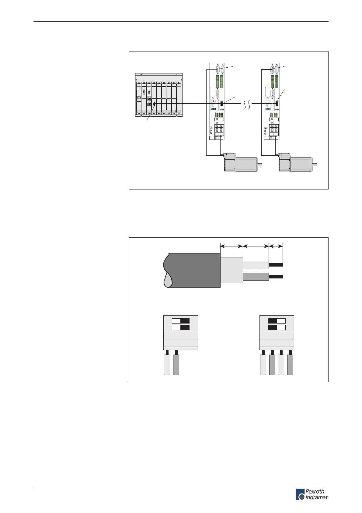
PLC control
PROFIBUS-DP
rst DKC03.1
last DKC03.1
Matching resistor
at the start of the
PROFIBUS line
must be set on ON
Matching resistor at
the beginning of the
PROFIBUS line must
be set to ON
1) Set matching resistor
to OFF
Fig. 4-187: An example of connecting a DKC03.3 to the PLC control via the
PROFIBUS-DP
The PROFIBUS connectors each have a connectable terminating
resistor. The terminating resistor must always be active at both the rst
and last bus stations. Do not interchange the A and B wires. Perform the
connection as shown in the gures below.
AP5069f1.fh7
OFF
ON
OFF
ON
Bus connection and switch
position for the rst and last stations
Bus connection and switch
position for all other stations
shield
A1 B1 A2 B2
5 16 5
A1 B1 A2 B2
Fig. 4-188: Preparing a cable for connecting a bus connector
customerservice@hyperdynesystems.com | (479) 422-0390

 Loading...