4-118 ECODRIVE03 DKC**.040, DKC**.100, DKC**.200 ECODRIVE03 Drive Controllers
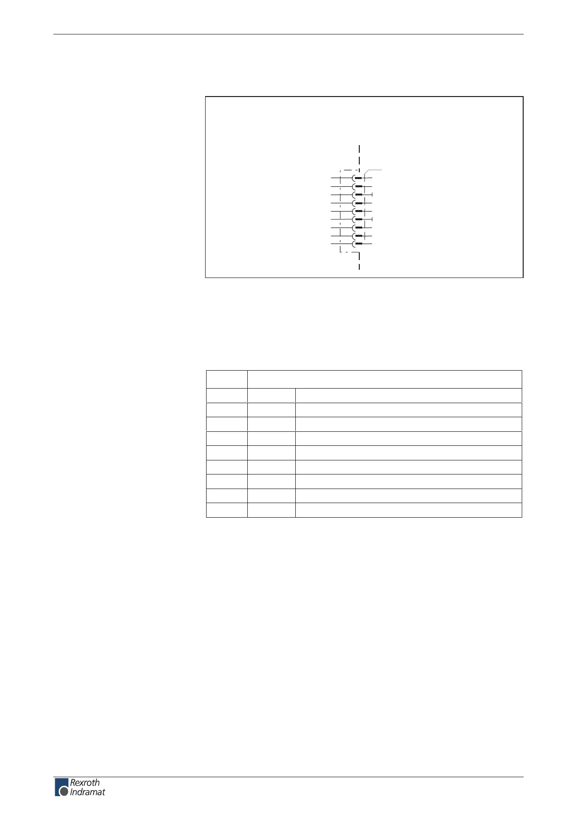
Connection diagram for CANopen Interface
DKC05.3
AP5163F1.FH7
n.c.
CAN_L
0V
n.c.
screen
0V
CAN_H
n.c.
n.c.
X50
1
2
3
4
5
6
7
8
9
device-external device-internal
CANopen interface
Fig. 4-202: CANopen interface for DKC05.3
as per ISO 11 898
as per ISO 11 898
noitinifeDniP
.c.n.c.n1
langis laitnereffiDL_NAC2
dnGV03
.c.n.c.n4
noitcennoc dleihSdleihs5
V0V06
langis laitnereffiDH_NAC7
.c.n.c.n8
.c.n.c.n9
Fig. 4-203: Interface signal allocation
Via D-subminiature mounting screws and metal connector housing.
The denition of the diagnostic displays are in the rmware function
description.
Connection
CANopen interface:
Interface compatibility:
Recommended cable:
Plug-in connector assignment
X50:
Shield connection:
Diagnostic display
H50 – H55:
customerservice@hyperdynesystems.com | (479) 422-0390
 Loading...

