June 21, 2002
Publication No. PI9780
2
PROGRAMMING
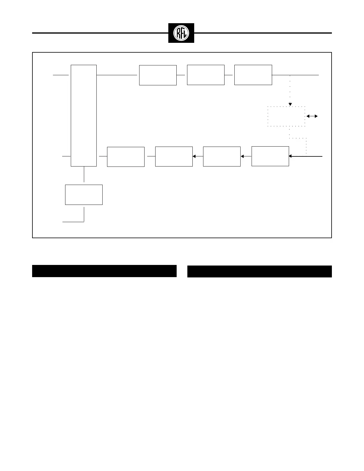
Figure 2. Block diagram, of typical RFL 9780 Programmable FSK Powerline Carrier System
The transmitter frequency and shift are selected by
programmable rotary type switches on the transmitter
module. The operating frequency can be programmed
from 30 to 535 kHz, in 10-Hz steps; frequency shifts of up
to ± 990 Hz can be programmed, in 10-Hz increments.
2F and 3F operation with different shift bandwidths are
also possible.
The receive frequency is set by DIP switches to any
frequency from 30 to 535 kHz, in 250-Hz steps.
STANDARD FEATURES
• Tested in compliance to the requirements specified
in ANSI C93.5 -1997 Single Function Powerline
Carrier transmitter/ Receiver equipment.
• ESD protection (per IEEE PC 37.90.3, draft A, 1/8/99)
• Tx/Rx, Tx/Tx, Rx/Rx, Tx only, and Rx only configura-
tions are supplied in an single three rack unit
chassis
• Compliant to C37.90.2. EMI Susceptibility Tested as
specified in ANSI C93.5 - 1997
• Programmable RF receiver input filter provides
improved noise rejection.
Logic
Module
▼
▼
▼
▼
▼
○○○○○○
▼
▼
▼
▼
▼
▼
▼
▼
▼
▼
▼
▼
Trip
Inputs
Trip,
Guard &
Alarm
Outputs
Optional
SOE/IRIG-B
RS-232
LIMITER/
SLICER
CLI with
Narrow Band
Filter
IF/BF
RF Interface
Filter
Optional
Hybrid
Output
Filter
10 Watt
Power Amp
Digital
Transmitter
Line
Coupling
Equipment
○○