June 21, 2002
Publication No. PI9780
3
STANDARD FEATURES CON’T.
1. Trip Key Input #1
2. Trip Key Input #2
3. Guard Output
4. Trip Output
5. Transmitter Fail
6. Logic Alarm
7. Low Level Alarm
8. Power-up
9. Power supply #1 Fail
10. Power supply #2 Fail
Table 2. SOE Data Points
• Redesigned logic module provides the following
user selectable functions:
Timer Total Duration Resolution
Pre Trip Timer 0 -31.75 msec 0.25 msec
Pre-Guard Timer 0 -31 msec 1.0 msec
Guard Hold Timer 0 -31 msec 1.0 msec
Trip Hold Timer 0 -310 msec 10 msec
Unblock Trip Window 50 -350 msec 50 msec
Unblock Security Timer 0 -70 msec 10 msec
Alarm Pick-Up Timer 50,100 -1500 msec 100 msec
Alarm Drop-Out Timer 50,100 -1500 msec 100 msec
Guard Before Trip Timer 50 -190 msec 10 msec
Trip After Guard Timer 50 -190 msec 10 msec
Bi-Polar Noise Detector 2 -14 msec 2.0 msec
Table 1. User Programmable Logic.
All timer values are factory set for optimum performance
for each application. All settings are recorded on
customer specific applications drawings.
• Each RFL 9780 station is pre-wired so that all input
and output connections for the standard features are
made to the same terminals on each station.
• All RFL 9780 stations are equipped with carrier level
indicators, a transmitter output power alarm, and a
low receiver input alarm as standard equipment.
Skewed or transformer hybrid modules are also avail-
able for use with the RFL 9780 and fit within the same
chassis.
Options for the RFL 9780 include permissive coordinat-
ing, and more. RFL’s sales and engineering staff can cus-
tom configure the 9780 for virtually any input, output, or
logic requirement, making it the most flexible single func-
tion powerline carrier system available to date.
The optional Sequence of Events (SOE) Module provides
a record of 40 events. Table 2 below, shows the data
points monitored for a standard TX/RX Terminal.
OPTIONS
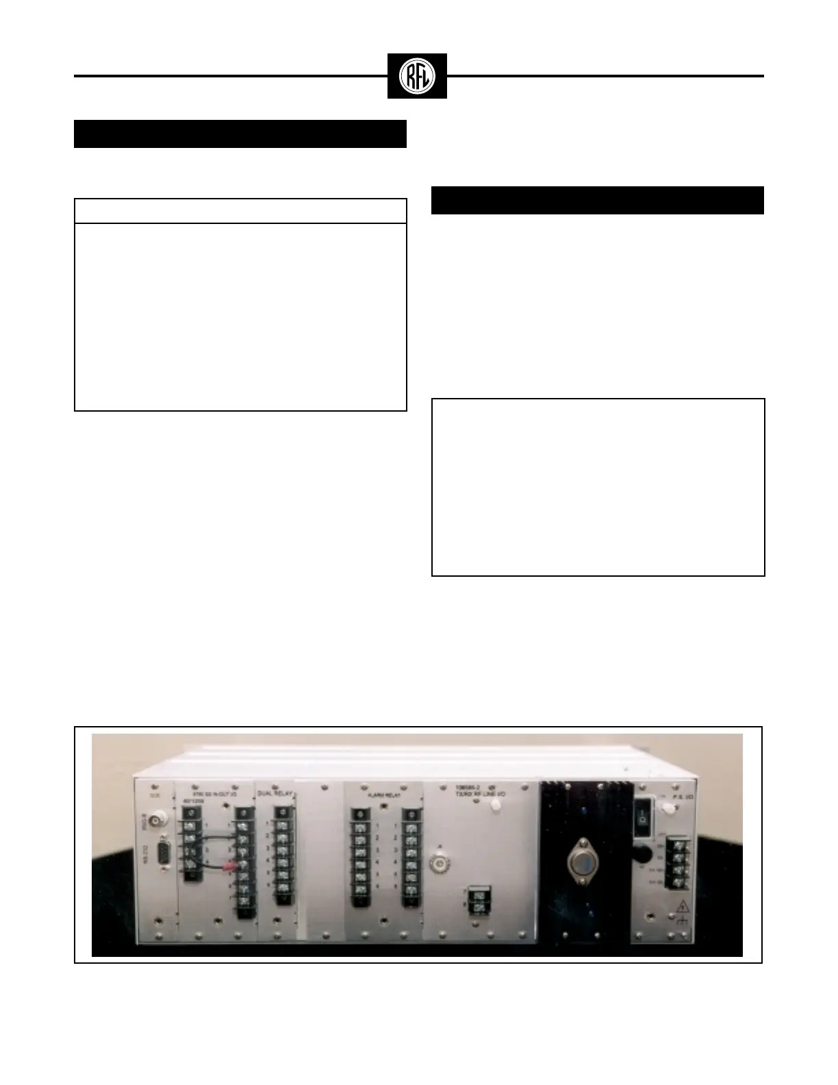
Figure 3. Typical RFL 9780 Programmable FSK Powerline Carrier System Rear View.
• 48V/125V and 250V internal power supply options.
Systems may be equipped with redundant supplies
in a single chassis.
Custom application requirements, such as functional
test panels, additional trip & guard contacts, redundant
channels, and 50 and 100 Watt RF power amplifiers can
be accommodated. Options may require an additional
accessory chassis.
• RF interface withstands a 3KV 1.2/50 µs pulse as
specified in C93.5-1997