Frequency
Shift
±Hz
Nominal
Bandwidth
Unidirectional
Channel
Spacing
100 Hz
250 Hz
500 Hz
12 ms
7 ms
5 ms
Table 3. Minimum permissible channel spacings
and delay times.
SPECIFICATIONS
June 21, 2002 Publication No. PI9780
4
200 Hz
500 Hz
1000 Hz
Delay
Time
500 Hz
1250 Hz
2500 Hz
Bi-Directional
Channel
Spacing
1000 Hz
2500 Hz
5000 Hz
General:
The 9780 is a programmable 10W FSK power line carrier
system which fully complies with ANSI C93.5. The
standard Tx/Rx system is packaged in a single 3U high
chassis and includes full-feature transmitter and receiver
sections. The unit may optionally be equipped with a
hybrid, SOE module, and redundant supply in the same
chassis. External amplifiers can be used to boost the out-
put power if required.
Dimensions: 19” x 5.25” x 15.25”
Supply voltage: 48/125 Vdc (38 to 150 Vdc, 85W)
250 Vdc (200 to 300 Vdc, 85W)
Weight: Approximately 18 lbs.
Operating Temperature: -20°C to 60°C
Humidity: 0 to 95% non-condensing
Dielectric and surge withstand: Per ANSI C93.5
ESD Protection: per IEEE PC37.90.3, Draft A, 1-8-99
Transmitter:
The transmitter is a fully programmable three-frequency
Direct Digital Synthesis (DDS) generator followed by a
10 W power amplifier and filter. The unit may be
configured for 1W/1W, 1W/10W, or 10W/10W operation
(for a two-frequency system, three-frequency systems
have additional modes).
Number of frequency presets: 3
Frequency step size: 10 Hz
Frequency setting method: Direct reading rotary
switches
Rated output power: 10 Watts rms
Output impedance: 50 Ohms
(with load-matching adjustment)
Receiver: The receive circuit consists of an input
normalizer, programmable frequency detector, and
carrier level indicator.
Receiver sensitivity: 5 mVrms
Maximum receive level: >25 Vrms
TX
TX
•
••
•
••
T
CF G
GCFT
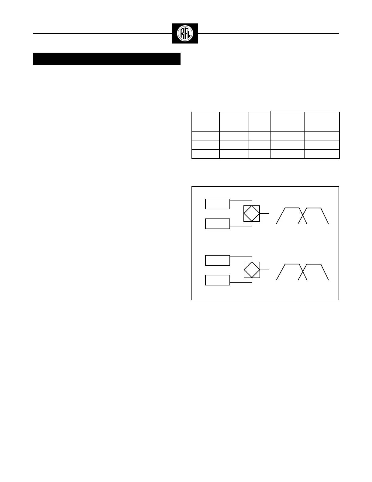
244.9 KHz
245.0
245.1
245.4
245.5
245.6
CH1
CH2
TX TX
A. Unidirectional system (500-Hz minimum spacing).
TX
Rx
•
••
•
••
T
CF G
GCFT
244.9 KHz
245.0
245.1
245.9
246.0
246.1
CH1
CH1
TX RX
B. Bi-directional system (1000-Hz minimum spacing).
RESISTIVE HYBRID
RF SKEWED HYBRID
Figure 4. Typical Channel Spacings.
Carrier Level Indicator:
Display: Front panel 3-1/2 digit direct reading (in dB)
Range: ±10dB
External meter output: 0 to 100 µAmp or ±1Volt, jumper
selectable
Receiver Logic Functions:
The FSK’s received signals are sent into a user
configurable logic module which processes the infor-
mation. Each of the individual timers and signal
qualifiers may be independently disabled or set to a
desired value (in mSec) see table 2.