Sequence of Events
The units may be equipped with a Sequence Of Events
(SOE) data log. System status points are checked every
millisecond and changes in system status (events) are
recorded in the log with time and date stamps. The events
are stored in non-volatile memory and are recalled most
recent event first. The forty most recent events are re-
tained. The local clock is automatically synchronized to
an externally supplied IRIG-B signal if available.
Clock functions: Y2K compliant
IRIG-B input: 1000 Hz modulated or direct TTL
Output Ratings
(2) Solid State Outputs
(1) guard, (1) trip:
Maximum continuous current: 1 Amp
Maximum 1 minute current: 2 Amps
Maximum 100 mSec current: 10 Amps
Maximum open circuit voltage: 280 Volts
(2) Form “C” Contacts/Relay Outputs
(1) guard (1) trip:
Maximum continuous current: 5 Amps
Maximum 200 mSec current: 30 Amps
Maximum open circuit voltage: 280 Volts
(5) Form ”C”: Alarm Relay Contact Outputs:
Tx Sent, PS Fail, Tx Fail, Low Level, Logic Fail
Maximum continuous current: 1 Amp
Maximum breaking current (125 Vdc):
1 Amp, non-inductive
Maximum breaking current (280 Vdc):
0.25 Amp, non-inductive
Maximum open circuit voltage: 280 Volts
Note: Logic level (5 volt nominal ) outputs are available.
RF Output
Maximum continuous output power: 10 Watts
Nominal output impedance: 50 Ohms (with matching
adjustment)
Input Ratings
(2) Trip key inputs 1 & 2
48 Volt Inputs
Will not operate at or below: 28 Volts
Will operate at or above: 35 Volts
Minimum pulse duration: 100 µSec
Input Current: <10mA, 5mA typical
125 Volt Inputs
Will not operate at or below: 70 Volts
Will operate at or above: 90 Volts
Minimum pulse duration: 100
µSec
Input Current: <10mA, 5mA typical
250 Volt Inputs
Will not operate at or below: 140 Volts
Will operate at or above: 175 Volts
Minimum pulse duration: 100
µSec
Input Current: <10mA, 5mA typical
Note: Logic level (5 volt nominal ) inputs are available.
RF Input
Input impedance (termination enabled): 50 or 75 Ohms,
selectable
Maximum continuous termination power dissipation: 1 W
Input impedance (termination disabled): >30 K-Ohms
Input Protection
>50 Vrms continuous without damage to receiver
(excluding termination resistors).
Input Surge
3KV per C93.5
June 21, 2002
Publication No. PI9780
5
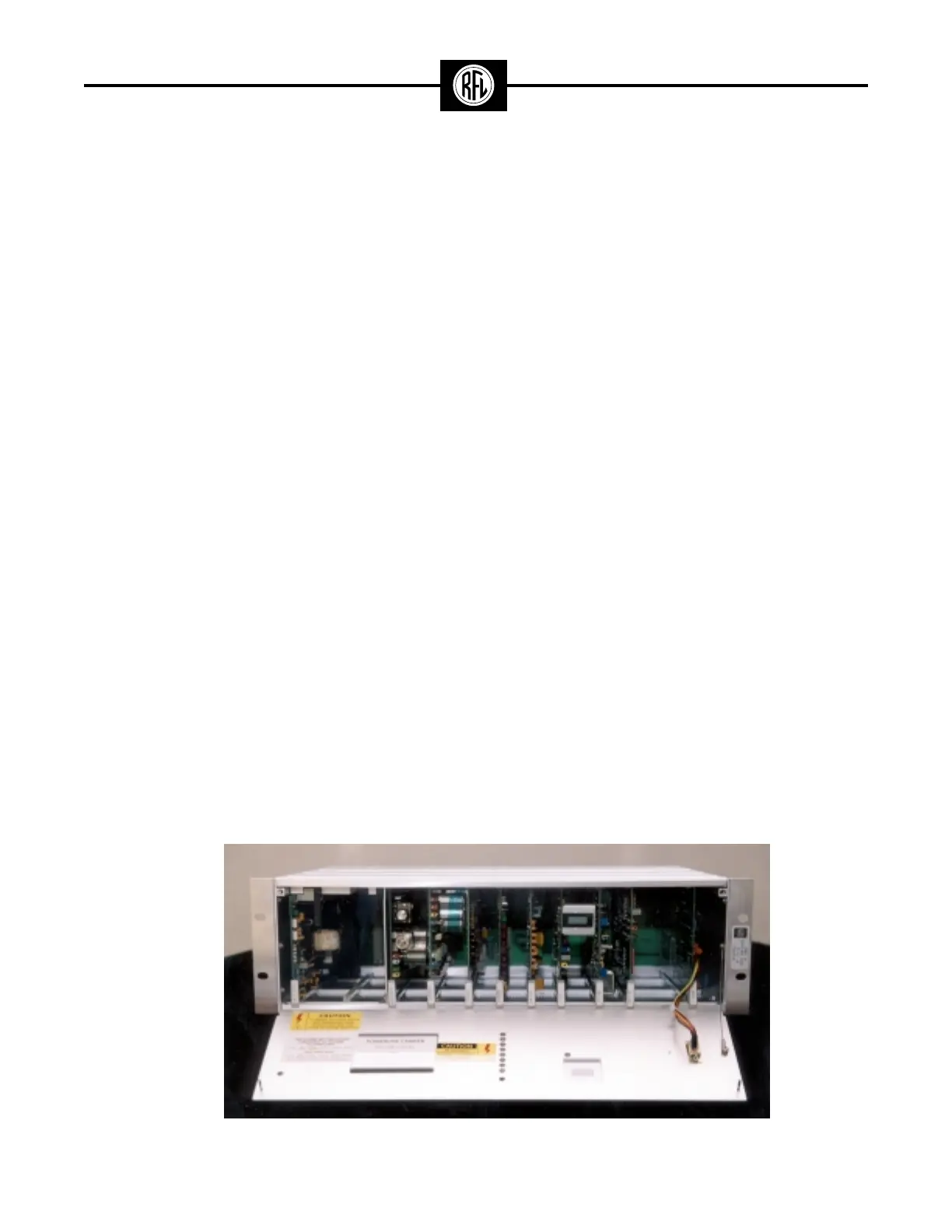
Figure 5. Typical RFL 9780 Programmable FSK Powerline Carrier Front Panel Down.