Standing Wave
Standing waves are a phenomenon that exist,
and are detrimental to transmission on all trans-
mission lines that are not terminated in their char-
acteristic impedance.
A line not properly terminated carries two sig-
nals; the transmitted signal and the reflected sig-
nal. At certain points along the line these sig-
nals are in phase and add, while at other points
they are out-of-phase and subtract. Part of the
power is reflected back and reflected waves cre-
ate a voltage standing wave pattern on the trans-
mission line.
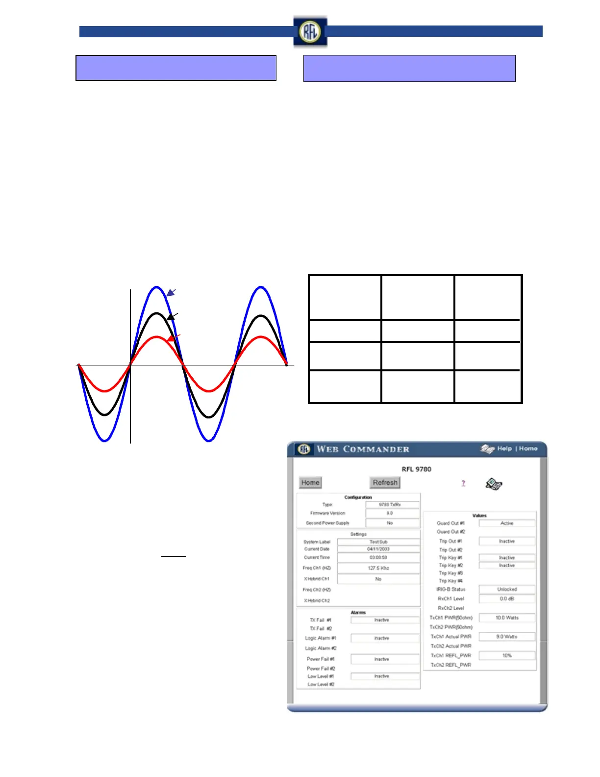
Standing wave
Incident wave
Reflected wave
Standing Wave
In the example shown above, the
Voltage Standing Wave Ratio (VSWR) is:
Line Impedance
The line impedance depends on type of conductor and
PLC coupling method. The range of characteristic line im-
pedance, at power line carrier frequencies, is from 200 to
800 ohms. Factors influencing the impedance are:
· Line resistance
· Line inductance
· Capacitance
· Conductor radius
· Height above the ground
· Phase separation
· Line taps
A tap can present a low impedance at the carrier
frequency depending on the length and termination.
Transmission Line
Conductor
Single Wire
Bundled Conductor
(2 Wire)
Bundled Conductor
(4 Wire)
Characteristic
Impedance Phase
to Ground Coupling
(Ohms)
350 to 500
250 to 400
200 to 350
Characteristic
Impedance Phase
to Phase Coupling
(Ohms)
650 to 800
500 to 600
420 to 500
Transmission Line Characteristic Impedance
2 +1
2 - 1
VSWR
=
3 : 1=
RFL Web Commander User Interface that includes Reflected
Power values:
Reflected Power Meter
Publication No. RFL RPM