RFL Reflected Power Meter
Reflected Power
A check of reflected power is an essential part of com-
missioning power line carrier equipment. An exces-
sive percentage (>10%) reflected power at the trans-
mitter indicates mismatch of impedances and should
be corrected by adjusting the line tuner.
The built-in Reflected Power Meter in RFL 9780/RFL
9785 makes this easy, both at commissioning and for
maintenance.
Weather and temperature changes affect the charac-
teristic impedance of the line and might warrant read-
justment of the tuner. The RFL Reflected Power Meter
can be read-off remotely and makes it easy to check
received signal level and reflected power during ad-
verse weather conditions without the need for travel-
ing to the substation.
The reflection coefficient r is simply a mismatch
seen at the line tuner. This is a complex number,
that varies from -1 for a shorted line to +1 for an
open line. For a matched load r is 0.
where
r = the reflection coefficient
Z = the load impedance
Z
0
= the line impedance
Return loss is a measure in dB of the ratio of power
in the incident wave to that in the reflected wave,
and it is always a positive value. A return loss of 10
dB means that 1/10
th
of the incident power is re-
flected. Return loss is related to the reflection co-
efficient by
r=
Z - Z
0
Z + Z
0
Reflected Power is the proportion of forward power
that is reflected back towards the transmitter by a
mismatched load, and is determined by the re-
flection coefficient at the load:
Voltage Standing Wave Ratio (VSWR) is the ratio
between the maximum to the minimum voltage.
The relationships between the standing wave ratio
(VSWR), the reflection coefficient (r), return loss
(R.L.) and reflected power (P
r
) are:
2
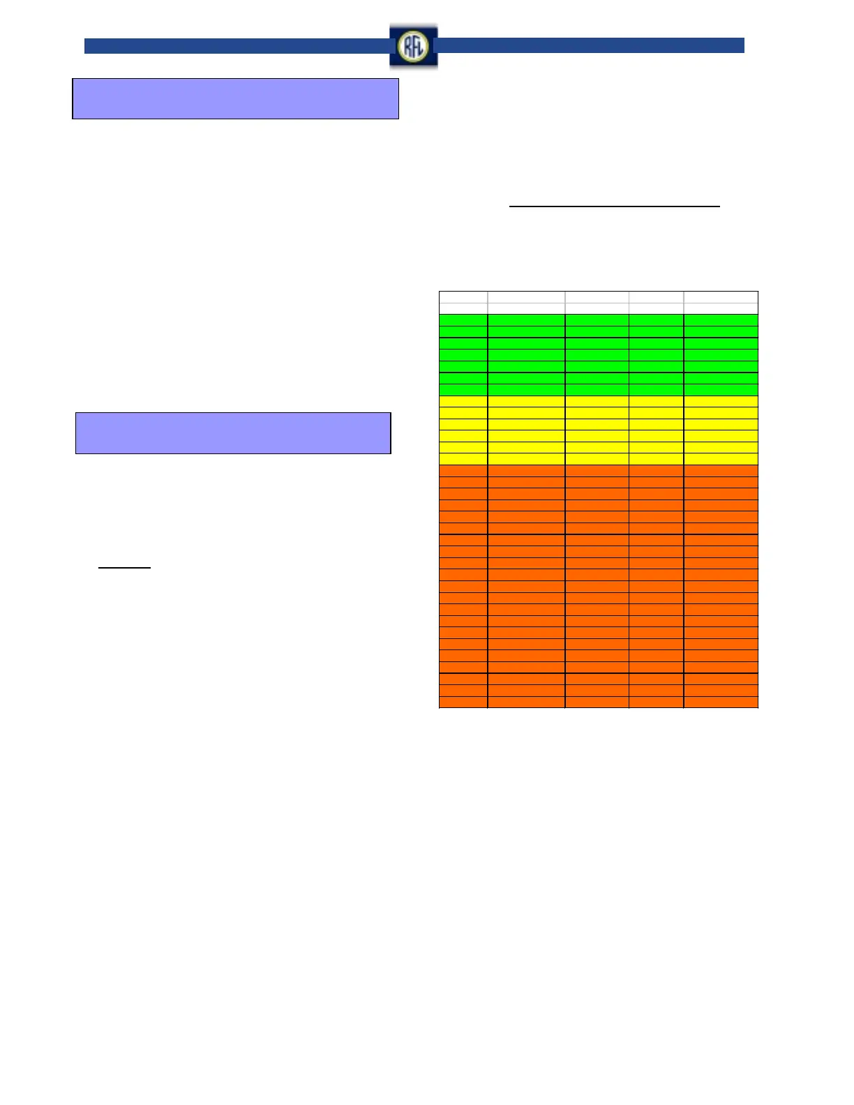
The values of reflected power are “good” if below
1%, “typical” (acceptable) if below 9% and “poor”
if above 9%.
As the loss is directly related to the reflected power,
measurement of reflected power and tuning to
minimize this value is an efficient way to obtain
optimum performance of the carrier channel.
VSW R Reflection Pow er
Coefficient Ratio
1.01 0.005 46.10 dB 0.00002 0.0020 %
1.02 0.010 40.10 dB 0.00010 0.0100 %
1.04 0.020 34.20 dB 0.00038 0.0380 %
1.06 0.029 30.70 dB 0.00085 0.0850 %
1.08 0.039 28.30 dB 0.00148 0.1480 %
1.10 0.048 26.40 dB 0.00227 0.2270 %
1.20 0.091 20.80 dB 0.00826 0.8260 %
1.30 0.130 17.70 dB 0.01701 1.7000 %
1.40 0.167 15.60 dB 0.02778 2.8000 %
1.50 0.200 14.00 dB 0.04000 4.0000 %
1.60 0.231 12.70 dB 0.05325 5.3000 %
1.70 0.259 11.70 dB 0.06722 6.7000 %
1.80 0.286 10.90 dB 0.08163 8.2000 %
1.90 0.310 10.20 dB 0.09631 9.6000 %
2.00 0.333 9.50 dB 0.11111 11.1000 %
2.20 0.375 8.50 dB 0.14063 14.1000 %
2.40 0.412 7.70 dB 0.16955 17.0000 %
2.60 0.444 7.00 dB 0.19753 19.8000 %
2.80 0.474 6.50 dB 0.22438 22.4000 %
3.00 0.500 6.00 dB 0.25000 25.0000 %
3.50 0.556 5.10 dB 0.30864 30.9000 %
4.00 0.600 4.40 dB 0.36000 36.0000 %
4.50 0.636 3.90 dB 0.40496 40.5000 %
5.00 0.667 3.50 dB 0.44444 44.4000 %
6.00 0.714 2.90 dB 0.51020 51.0000 %
7.00 0.750 2.50 dB 0.56250 56.3000 %
8.00 0.778 2.20 dB 0.60494 60.5000 %
9.00 0.800 1.90 dB 0.64000 64.0000 %
10.00 0.818 1.70 dB 0.66942 66.9000 %
15.00 0.875 1.20 dB 0.76563 76.6000 %
20.00 0.905 0.90 dB 0.81859 81.9000 %
30.00 0.936 0.60 dB 0.87513 87.5000 %
40.00 0.951 0.40 dB 0.90482 90.5000 %
50.00 0.961 0.30 dB 0.92311 92.3000 %
Return
Loss (dB)
Percent
Reflected
R.L. = -20 log
10
( r)
r (%) = 100 P
2
r
r
2
Incident Wave + Reflected Wave
Incident Wave - Reflected Wave
VSWR
=
Reflected Power Relationship Chart
RFL Electronics Inc.
(973) 334-3100
February 2003