Home
Ricoh
Printer
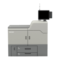
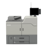
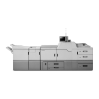
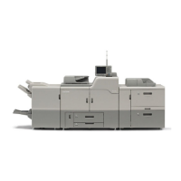
PRO C7210
Ricoh PRO C7210
685 pages
Manual
To Next Page
To Next Page
To Previous Page
To Previous Page
Loading...
3.T
roublesho
oting: Pap
er Delivery
Problems
453
Cleaning t
he Paper Exit
Inverter
Roller
1.
P
ull out the
left drawer
.
2.
Open the exit guide (D
5).
3.
R
emove
the C1 lever
[A].
4.
R
emove
the left drawer
cover
[B].
456
458
Table of Contents
Main Page
1. SC Codes
11
Self-Diagnostic Mode
11
Service Call Conditions
11
SP descriptions: SP5-875-001 (SC automatic reboot: Reboot Setting)
12
SC Logging
12
SC Automatic Reboot
12
Screen display during reboot
13
Operation during SC reboot
13
SC Manual Reboot
14
Service Call 101-195(Scanning)
16
SC100 (Engine)
16
Service Call 202-286 (Image Writing)
27
SC200 (Engine)
27
Service Call 300-398
35
SC300 (Engine: Charge, Development)
35
Service Call 400-498
55
SC400 (Engine: Around the Drum)
55
Service Call 501-595
68
SC500 (Engine: Paper transport 1: Paper Feed, Duplex, and Transport)
68
Service Call 600-672 (Controller)
123
SC632 to SC653, SC670 to SC672
123
Service Call 603-689 (Engine)
126
SC600 (Engine: Communication and Others)
126
Service Call 700-740
152
SC700 (Engine: Peripherals)
152
ADF
152
Finisher/ Booklet Finisher
156
Multi-Folding Unit
175
High Capacity Stacker
183
Trimmer Unit
191
Cover Interposer Tray
193
Service Call 750-790
197
SC700 (Engine: Peripherals)
197
Perfect Binder
197
Ring Binder
355
Vacuum Feed LCIT
366
RPIP Interface Box
375
Toner Interchange Unit Type S9
376
Service Call 816-899
377
SC816 to SC899
377
Service Call 900-998 (Controller)
381
SC900 to SC998
381
Service Call 995 (Engine)
390
SC995 (Engine: Others)
390
2. JAM Codes
391
Jam Detection
391
Jam Displays
391
Jam Removal
391
Printer Engine Jam History
392
How to check
392
Display
392
Jam Code Descriptions
392
ADF
392
Main Machine+A3 LCIT
393
Vacuum Feed LCIT
396
Vacuum Feed LCIT (2nd)
396
Vacuum Feed LCIT (3rd)
397
Cover Interposer
398
Finisher/Booklet Finisher
399
Multi-Folding Unit
400
High Capacity Stacker 1 (Upstream)
401
High Capacity Stacker 2 (Downstream)
402
Trimmer Unit
402
Ring Binder
403
Perfect Binder
404
Buffer Pass Unit
405
RPIP Interface Box
405
Others
406
3. Troubleshooting: Paper Delivery Problems
407
Paper Feed Problems on Main Machine
407
Frequent Paper Misfeeds
407
Coated or another type of unsupported paper is loaded in the machine's tray.
407
The side fences in the paper tray are too close together.
407
The side fences in the paper tray are too far apart.
407
The paper size/orientation/type is not specified correctly.
407
Too many sheets of paper are loaded in the paper tray.
407
The edges of the sheets are rough.
407
Sheets are curled or wavy.
407
Sheets absorbed moisture and became limp.
407
When using thick paper or slippery paper.
408
The paper feed sensor is stained with paper dust.
408
The paper feed performance is less sufficient because the paper transport roller is soiled with toner.
408
The transfer timing motor is not operating correctly (also applies to when paper is fed from LCIT).
408
Accuracy" is selected for the transfer timing sensor for printing on paper other than white.
408
No Feeding (Poor-Quality Paper): Main Machine Paper Feed
408
J032 Appears
410
Cause
410
This is likely to occur if:
410
Solution
411
J033/J082 Appears (Small size paper, Metallic Paper, and Paper Weight 7 or larger)
411
Cause
411
This is likely to occur if:
412
Solution
413
When Paper Other Than Envelope Is Used
413
When Envelope Is Used
414
J080 Appears (Paper Delay in Specific Papers)
415
Cause
415
This is likely to occur if:
415
Solution
415
J099 Appears (Main Machine Tray)
415
Coated or another type of unsupported paper is loaded in the machine's tray
415
Sheets are stuck to each other
415
The edges of the sheets are rough.
417
Wrong Detection of Double Feeding
417
When using thin paper such as paper thickness 1 (52.3 to 63.0g/m2);
417
The Double-Feed Sensor is dirty with paper powder;
417
Setting [Double Feed Detection] to OFF
417
Cleaning the Double-Feed Sensor
417
Paper Skew
419
Cause
419
Solution
420
Adjusting the Rotary Gate Position
420
Overview of adjustment
420
J097 (Overskew)/ J098 (Shift Over) Appears
423
J097 (Overskew)
423
J098 (Shift over)
424
Cause
424
Solution
425
When using the Generic Paper Setting
425
When using the Custom Paper Settings (IMSS).
426
Cleaning the CIS
427
Efficient SP for Paper Jam Analyzing
429
Paper Transport Problems on Main Machine
430
Fan on Optional Buffer Pass Unit Generates Noise
430
Solution
430
White Spots/Scratches Due to Paper Dusts
430
Cause
430
Solution
430
Cleaning the Transfer Unit
431
Cleaning the Paper Tray Unit of Main Machine
434
Cleaning the LCIT (RT5110) Paper Tray
436
Cleaning the Paper Feed Unit of Vacuum Feed LCIT (RT5120)
438
Cleaning the Bridge Unit
441
Cleaning the Paper Feed Unit of the Multi Bypass Tray (BY5020)
442
Roller Marks on Paper Edges (Merge)
443
Cause
443
This is likely to occur if:
444
Solution
444
Roller Marks on Paper Edges due to the dirt on transfer roller
444
Solution for roller mark on paper trailing edge due to decurl unit
445
Solution for roller mark due to dirt on anti-static brush
445
Cleaning the Optional Buffer Pass Unit
446
Cleaning the Duplex Guide Plate
447
Disturbed Images, Scratches, Streaks, Waves and Creases (Line Speed Fine-tuning)
448
Cause
448
Solution (1)
449
If Transfer roller rotates too fast;
449
If Transfer roller rotates too slow;
450
If Exit roller is dirty;
450
Solution (2)
450
Adjustment through Custom Paper Settings (Scratches/Streaks on Side 2)
451
Adjustment through Custom Paper Settings (Scratches/Streaks or Creases appear on Side 1)
451
Solution (3: Service Only)
451
Adjustment through SP (Scratches/Streaks on Side 2)
452
Adjustment through SP (Scratches/Streaks or Creases appear on Side 1)
452
Cleaning the TIM-Mag Unit Entrance Roller
453
Cleaning the Cooling Belt
454
Cleaning the Paper Exit Relay Roller
455
Cleaning the Paper Exit Roller
456
Cleaning the Paper Exit Inverter Roller
457
Scratches, Streaks, Waves or Creases (Decurl Unit Line Speed Adjustment)
458
Cause
458
Solution
459
If Scratch/Streak on Side 2, or chattering noise occurs;
459
If Scratch/Streak on Side 1, or copied paper has creases;
459
Curl does not disappear even though a decurl unit is installed:
459
Roller Marks by Paper Exit Inverter Roller
460
Cause
460
This is likely to occur if:
460
Solution
460
Roller Marks on Coated Paper (after Continuous Large-volume Printing)
461
Cause
461
This is likely to occur if:
461
Solution
461
Fusing Jam When Printing with High Coverage (J033/J034/J083)
462
Cause
462
This is likely to occur if:
462
Solution
463
Flowchart for Decreasing Set Temperature
464
Jams Related to insufficient Separation on Thin Paper
464
Cause
464
This is likely to occur if:
465
Solution
465
If the mask width of paper leading edge can be widened, or the erase margin of trailing edge can be widened;
465
If the mask width of paper leading edge cannot be widened, or the erase margin of trailing edge cannot be widened;
465
Jams Related to Duplex/Invert in Short Grain and Thickest Paper
466
Cause
466
This is likely to occur if:
466
Solution
466
Roller Marks on Buffer Pass Unit
466
Cause
467
This is likely to occur if:
467
Solution
467
Flowchart for Decreasing Set Temperature
468
Paper Feed/Transport Problems on Peripherals
469
Common: A3LCIT /Bypass Tray /Cover Interposer Tray
469
Cause
469
Solution
469
No Feeding (Envelope)
470
Cause
470
This is likely to occur if:
470
Solution
470
No Feeding 1
470
Cause
470
Solution
470
A3 LCIT
471
Bypass Feed Tray
472
Cover Interposer Tray
473
No Feeding 2
473
Cause
473
This is likely to occur if:
473
Solution
473
Attaching the Tab Sheet Holder (A3 LCIT)
474
Cleaning the Paper Feed Path
475
Cleaning the Paper Feed Path in the A3 LCIT (Trays 3-5)
475
Cleaning the Paper Feed Path in the Multi Bypass Tray (Tray 6)
477
Cleaning the Paper Feed Rollers and Paper Feed Belt in the Cover Interposer
480
No Feeding 3
481
Cause
481
This is likely to occur if:
481
Solution
481
Adjusting the Upper Limit Position (A3 LCIT)
481
Effect of Adjusting the Upper Limit Position
481
[For repeated feeding problems due to double feeding or double feeding as a bundle]
484
[When repeatedly fails to feed]
485
No Feeding 4
486
Cause
486
This is likely to occur if:
486
Solution
486
Adjusting the Upper Limit Position (Bypass Tray)
487
Effect of Adjusting the Upper Limit Position
487
[For repeated feeding problems due to double feeding or double feeding as a bundle]
490
No Feeding 4 (Cover Interposer Tray)
490
Cause
490
This is likely to occur if:
490
Solution
490
No Feeding (Poor-Quality Paper): 3-Tray A3LCIT
492
4. Troubleshooting: Post-Processing Option
494
Finishing Problems: Finisher/Booklet Finisher
494
Large Paper Not Stacked Properly
494
Cause
494
This is likely to occur if:
494
Solution
496
SPs
497
When bundle to be bound is poorly aligned
497
Cause
498
This is likely to occur if:
498
Solution
498
Trailing Edge of Stapled Sheets Close to the Paper Exit
499
Cause
499
This is likely to occur if:
499
Solution
499
Leading edge 4mm pitch edges getting dirty
500
Cause
500
This is likely to occur if:
500
Solution
501
Paper edges get dirty caused by dirt of paper transfer rollers
502
Location Occurs
502
Cause
502
This is likely to occur if:
502
Solution
502
Only the Cover Is Discharged During Saddle Stitching (JAM129)
503
This is likely to occur if:
504
Solution
504
Thin, Coated Paper Eject Error (Stapled Sheets)
504
Cause
505
This is likely to occur if:
505
Solution:
506
Cleaning the Rollers and Guide Boards in the Finisher
507
Roller
507
Guide Board
507
Finishing Problems: Multi-Folding Unit
511
Folded Sheets Are Not Stacked Properly
511
Cause
511
Solution
511
Z-Folding Is Not Performed Correctly
511
Solution
512
Matte Paper Scratched During Folding
512
Cause
513
Solution
514
Folds Soiled by Multi-Sheet Folding
515
Cause
515
Solution
515
Edges of Letter Fold Bent
516
Solution
517
Poor Folding
517
Cause
517
Solution
517
Folding Deviation
518
Cause
518
<Folding deviation sample of L2 for Z-fold>
519
Solution
519
L1
519
L2
520
L3
520
Finishing Problems: High Capacity Stacker
524
Premature Detection of Full When Paper Discharged to Shift Tray
524
Cause
524
This is likely to occur if:
524
Solution
525
Marks Left by the Paper Holder
525
Cause
525
Solution
526
Prevent Loosening of Screws to the Cart's Handle
526
Cause
526
This is likely to occur if:
526
Solution
526
Finishing Problems: Ring Binder
528
SC756-48 (Ring Binder Is Not Detected)
528
Cause
528
Solution
528
5. Troubleshooting for the Operation Panel
529
Factory Reset
529
Factory Reset Procedure
529
Restoring after the Factory Reset
530
When updating the operation panel firmware and the application one by one
530
When using package update
531
Software Update Errors
532
Errors that occur during application update from an SD card
532
Errors that occur during update from the eDC Server
533
Errors That Occur When the Operation Panel Downloads Data from the Controller at Startup
535
6. Improving Throughput
536
Improving Throughput
536
Reducing the Waiting Time
536
Cause
536
Solution
536
Improving Fusing Capability
537
Cause
537
Solution
537
Improving Productivity when Loading the Different Types/Thicknesses of paper
538
Cause 1
538
Cause 2
539
Solution
539
Solution for Cause 1
539
Solution for Cause 2
539
7. Detailed Procedures of SC Occur
540
Detailed Procedures of SC Occur
540
Recovering SC499-03, Preventive Maintenance of Intermediate Transfer Scale
540
Cause
540
Solution
540
Intermediate Transfer Belt: How to Clean the ITB Speed Feedback Sensor
540
After cleaning the ITB Speed Feedback Sensor
543
SC441: ITB Drive Motor Error Measure Flow
544
Procedure: 1
544
Procedure: 2
545
Recovering from SC756-48
545
Recovering from SC486
546
Cause
546
Solution
546
8. Troubleshooting: Image Quality Problems
547
Image Index
547
Large classification: Lines/Streaks
547
Middle classification: Streaks
547
Middle classification: Bands
548
Large classification: Spots
550
Middle classification: Spots
550
Large classification: Full page
551
Middle classification: Unprinted
552
Middle classification: Unevenness
553
Middle classification: Dirtied printouts
555
Middle classification: Disturbed image
556
Middle classification: Scratches
557
Middle classification: Shifted image
557
Others
558
9. Image Quality Problem: Lines
559
Streaks
559
Horizontal Black Streaks (Image Edge)
559
Cause
559
This is likely to occur if:
559
Solution
560
Horizontal White Streaks
560
Cause
560
This is likely to occur if:
561
Occurrence condition (criteria)
561
Solution
561
Whiter at the Trailing Edge
561
Cause
562
This is likely to occur if:
562
Solution
562
Vertical Black Streaks
563
Cause
563
This is likely to occur if:
563
Solution
564
Vertical Black (color) Streaks (1)
565
Cause
565
Sample photos of scratches and foreign objects on the surface
565
This is likely to occur if:
567
Solution
568
Chart 1
568
Vertical Black (color) Streaks (2)
569
Cause
570
Solution
570
Vertical White Streaks (1)
570
Cause
571
Solution
572
Chart 1
572
Chart B
576
Vertical White Streaks (2)
578
Cause
578
This is likely to occur if:
578
Solution
578
Vertical Black Streaks Occur after "10: Exe Image Quality Adj Print: Acr Fd" is Executed
579
Cause
579
Solution
579
Bands
581
Banding (General)
581
Solution
581
Banding (63 mm intervals)
582
Cause 1: Uneven density at 63mm intervals caused by the difference in line speed
582
Cause 2: Uneven density at 63mm intervals caused by the paper transfer bias
582
Solution
583
Uneven Density at 63mm Intervals Caused by the Difference in Line Speed
583
Uneven Density at 63mm Intervals Caused by the Paper Transfer Bias
584
Banding (189 mm intervals)
584
Cause
584
This is likely to occur if:
585
Solution
585
10. Image Quality Problem: Spots
586
Spots
586
Black (color) Spots (1)
586
Cause
586
Solution
586
Test Printing and Checking Interval of Color Spots
586
[A]: Spots Interval for Approx. 189mm
587
[B]: Spots Interval for Approx. 40mm
588
Black (color) Spots (2)
589
Cause
589
This is likely to occur if:
589
Solution
590
White Spots/Toner Blasting
591
Cause
591
This is likely to occur if:
591
Solution
592
Medaka (White Spots)
593
Cause
594
Solution
594
Patchy Image at the Leading Edge
594
Cause
595
This is likely to occur if:
595
Solution
596
11. Image Quality Problem: Full Page
597
Unprinted
597
Fainter Leading Edge
597
1. Unprinted area on leading edge due to insufficient transfer pressure
597
2. Unprinted area due to insufficient transfer current
597
3. Unprinted area due to excessive transfer
597
This is likely to occur if:
598
Solution
598
1. Adjusting the gap of paper transfer
599
2. Adjusting the target constant voltage
600
Fainter Trailing Edge
600
Cause
601
Solution
601
Adjusting the paper transfer current at the trailing edge
603
Unprinted: When Using a Transparent Film
603
Cause
604
This is likely to occur if:
604
Solution 1 (Moving the image away from the paper edge by at least 5 mm)
604
Solution 2 (Replacing the PTR springs)
604
Unprinted: Around Clear-toner Images
605
Cause
605
This is likely to occur if:
606
Solution
607
Toner refresh procedure
607
Worm Holes: Text or Edge of an Image
608
Cause
608
This is likely to occur if:
609
Solution
609
Worm Holes: When Using the Clear Toner
612
Cause
613
This is likely to occur if:
613
Solution
614
Replacing the PTR springs
617
Uneven Density
622
Low Image Density of Black Area
622
Cause
622
This is likely to occur if:
622
Solution
622
Horizontal White Streaks: Around Black Text
622
Cause
623
Actions to take when the Toner Interchange Unit is installed
623
Solution 1 (Adjusting the Image Transfer Output for Black)
624
Solution 2 (Toner Refreshing)
625
Solution 3 (Increasing the black toner adhesion)
625
Solution 4 (Printing Black using a four-color)
625
Uneven Density between Left and Right of an Image: 40 mm Interval
626
This is likely to occur if:
626
Solution
626
Uneven Density within 90 mm of the Trailing Edge
627
This is likely to occur if:
627
Solution
628
Mottling
629
Cause
630
This is likely to occur if:
630
Solution
630
Improving usage environment
633
Increasing Toner Adhesion
634
Blurred Image: Around a Clear Image
635
Cause
635
This is likely to occur if:
635
Solution
636
Residual Gloss (Gloss Ghost)
636
Cause
636
This is likely to occur if:
637
Solution
637
Chart A
638
Flowchart for Decreasing Set Temperature
639
Residual Gloss (Gloss Ghost): Multiple
639
Cause
640
Solution
640
Chart A
641
Chart B
641
Uneven Gloss: Partly
642
This is likely to occur if:
642
Solution
642
Uneven Gloss: Wavy
642
Cause
643
This is likely to occur if:
643
Solution 1
644
Uneven Gloss: Side 2
644
This is likely to occur if:
645
Solution
646
Flowchart for Decreasing Set Temperature
647
Dirtied Printouts
648
Trailing Edge Dirty at 20 mm Intervals
648
Cause
648
Solution
648
Solution 1
648
Solution 2
648
Dirty Background
648
This is likely to occur if:
649
Solution 1
649
Solution 2
649
Toner Scattering: Lines
650
This is likely to occur if:
650
Solution 1 (Improvement by adjusting the image transfer output)
651
Solution 3 (Improvement by setting the paper transfer output (low pressure mode))
651
Solution 3 (Improvement by replacing the PTR springs)
652
Solution 4 (When toner scattering occurs on a line in the leading edge area of the paper)
652
Toner Scattering: Trailing Edge
652
Cause
653
This is likely to occur if:
653
Solution
653
Adjustment of Image Transfer Output
654
Adjusting the Print Speed
654
Replacing the ITB Guide Plate
655
Toner Scattering: Around a Solid Fill Image
655
Stained Paper Edges
655
Solution
656
Toner Stains on trailing Edge of think paper
657
Cause
658
Solution
658
Scratches, Others
660
Narrow Trailing Edge Margin (Image Elongation)
660
Cause
660
Solution
660
Uneven Gloss Waves at Paper Trailing Edge (When Paper Longer than A4 SEF Is Used)
660
Cause
661
Solution
661
Matte Paper Scratched During Folding
661
Insufficient Gloss: Clear Image
661
Cause
662
This is likely to occur if:
662
Solution
662
Milky Transparency
662
This is likely to occur if:
663
Solution
664
Flowchart for Decreasing Set Temperature
665
12. Advanced Instructions
666
Shortening the Leading/Trailing Edge Margins
666
Life Prediction of Developer
667
Capturing the Engine Debug Log
668
Overview
668
1. Capturing Log Function
668
2. Service Slot Board (SDCU)
668
3. Debug Cable
669
Procedures for Capturing the Engine Debug Log via the Capturing Log Function
669
Procedures for Capturing the Engine Debug Log via the Service Slot Board (SDCU)
669
Procedures for Capturing the Engine Debug Log via the Debug Cable
670
Capturing the TDCU Log
672
Procedures for Capturing TDCU Log
672
Capturing Other Logs
674
Duct Covers to Reducing Noise Level
675
Procedure
675
13. Fuses
680
Fuses
680
Boards Layout
680
PSU1(5V)
681
PSU2
681
PSU3
682
PSU4
683
PSU5
683
AC Drive
684
ACRY
684
RYB
685
RTB Links
1
Caution when installing the operation panel(RTB 14)
1
The Charge Roller Lever damaged(RTB 17)
1
Toner scattering (RTB 18a)
1
Unwanted line along the feed direction caused by main scan shading correction(RTB 19)
1
Part Replacemnt Alert Display Correction(RTB 20)
1
Other manuals for Ricoh PRO C7210
Operating Instructions
348 pages
Related product manuals
Ricoh PRO C7210X
348 pages
Ricoh PRO C7210S
552 pages
Ricoh PRO C7200
348 pages
Ricoh PRO C7200X
348 pages
Ricoh PRO C7200S
552 pages
Ricoh PRO C751
542 pages
Ricoh Pro C7100
212 pages
Ricoh Pro C7110x
212 pages
Ricoh Aficio SP C730DN
100 pages
Ricoh C2000
145 pages
Ricoh SP C252DN
208 pages