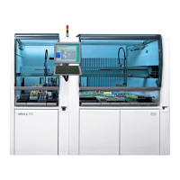
cobas p 512 Part F - Appendix
Operator's Manual – Version 1.6 - 10/2015 6-19
System status: system operations have been halted; user intervention
in the sorting area is possible.
Button on the screen which causes the system to switch to Standby
File (program) that is executed during the startup of the computer.
Stepper motor control board
Electronic PCB for stepper motor control.
A series of programs or commands under a main menu point.
Fluid required for pipetting and rinsing the fluid system;
typically distilled or demineralized water.
Naming conventions for test abbreviations, between the system and
the lab host.
Average number of primary samples processed per hour.
Prevents the racks from tilting when being moved from the input
station to the rack transport.
A tapered plastic cone that fits on the end of a pipetting unit. Tips are
disposable and single-use only.
Total volume of the disposable tip consisting of the application vol-
ume and dead volume.
Transfer position (input
position, feed-in)
Position at which the Hitachi five-slot racks are moved from the input
module onto the conveyor.
Transfer position (output
position)
Position at which the Hitachi five-slot racks are moved from the
conveyor into the output module.
The attachment on the sorting area on which the rack trays stand.
Optical unit that recognizes if a tube is positioned in the rack.
System to transfer the system fluid within the aliquoter system.
The twin tube conveyor transports the newly produced twin tubes.
Transfer of data to another system.
Person who uses and operates the aliquoter system.
Equipment required to control the operations of the system.
Design of the application programs and computer communication on
the monitor.
Physical position of the stepper motor, when the pipetting unit is
positioned in the waste tube for rinsing.
Part into which disposable tips are dropped by the pipetting unit.
Name of a work process which will be started by the user (see ‚Work
step‘ too).
Software program for executing specific tasks and process steps.
After switching on the aliquoter system, the work step [Work Cycle]
is displayed which depends on the status of the system that prevailed
before the system was switched off.

 Loading...