Part B - System description cobas p 512
2-32 Operator's Manual - Version 1.6 - 10/2015
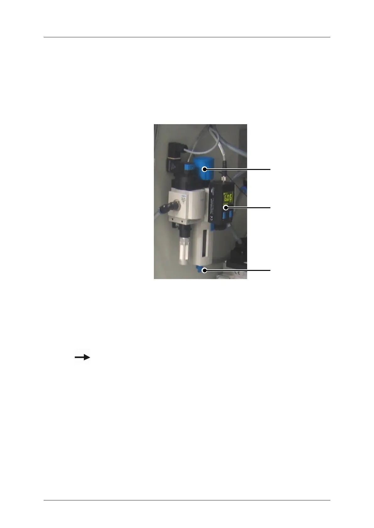
2.2.19 Air pressure maintenance unit (interior)
The compressed air maintenance unit with pressure control valve for the system pressure, a
compressed air filter with automatic emptying of condensation, and two manometer
switches are all mounted in the interior by the compressed air connection. The manometer
switches monitor the pressure of the compressed air supply and report to the system if there
is insufficient pressure or the pressure is set too high.
Figure 2-30: Maintenance unit with valve terminal
Under the compressed air maintenance unit is located a plastic container which receives the
condensate. This container should be emptied when necessary.
For further information please refer to Chapter 4 'Maintenance'.
B
 Loading...