cobas p 512 Part B - 0BSystem description
Operator's Manual - Version 1.6 - 10/2015 2-29
2.2.17 Compressed air connection
The compressed air connection is found on the rear of the cobas p 512.
Compressed air is required to drive mechanical components on the system. The system is
equipped with its own compressed air supply connection point, which is located on the
bottom right at the rear of the module. The system can also be connected to an existing
compressed air connection or a compressor at the customer's site.
The cobas p 512 requires dry, oil-free air and an air pressure of min. 6 to max. 8 bar. It
connects via a snap-on hose coupling NW 7.2 (G ¼').
Connect the air hose before starting the system.
2.2.17.1 Connecting the compressed air connection
1. Ensure that the air hose cannot be kinked or jammed during operation.
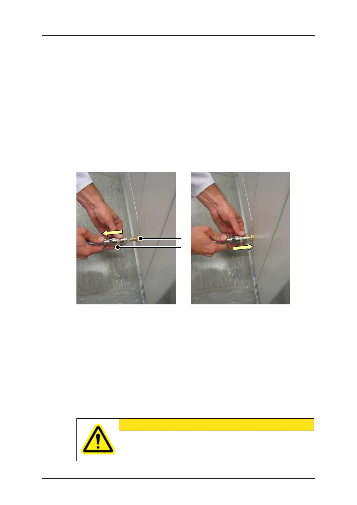
2. Route the hose coupling of the compressed air supply to the compressed air connection
point of the system. Hold the hose in both hands.
2-25: Preparing to connect the
compressed air hose
2-26: Connecting the compressed air
hose
Intake for compressed air supply
3. Pull back the sleeve of the hose coupling (towards yourself).
4. Insert the hose coupling as far as it will go onto the connection for compressed air supply
of the cobas p 512.
5. Release the sleeve of the hose coupling allowing it to slide forwards. The compressed air
hose is now connected.
6. Turn on the connected air compressor or the building's compressed air supply.
CAUTION
Damage can result if the air pressure is too high. The pressure control valve
must be set to 6 bar to operate the system.
 Loading...