cobas p 512 Part B - 0BSystem description
Operator's Manual - Version 1.6 - 10/2015 2-7
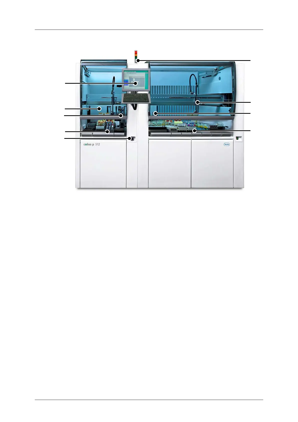
Figure 2-1: cobas p 512 system
Recapping module (optional)
The system consists of the following components:
• Input and output sorter
• Tube transport
• Camera system
First option: Camera system with BlueLYNX-220CX camera for tube cap recognition.
The system in located in the camera enclosure in the input sorter.
Second option: Camera system for tube recognition and serum fill-level recognition.
Camera system with Hitachi HV-D30 camera in camera enclosure and additional PC
located in the lower part of the output sorter enclosure. Image processing is conducted in
the PC with Windows® operating system and then transferred to the system.
• Decapping module
• Recapping module (optional)
• Control unit
 Loading...