COMMAND RANGING & TELEMETRY UNIT CORTEX
CRT QUANTUM USER'S MANUAL
Ref. DTU 100042
Is.Rev. 5.17
Date: Dec.
03, 2021Sept. 30, 2021
This document is the property of Safran Data Systems.
It cannot be duplicated or distributed without expressed written consent.
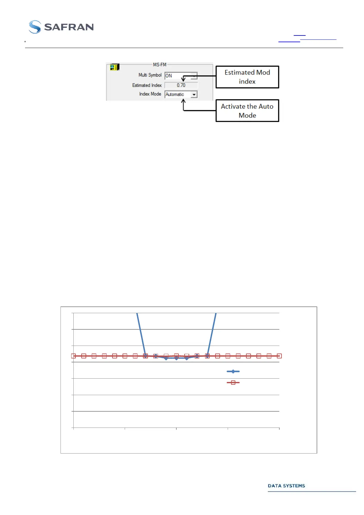
Note 1: Modulation Index impact on BER measurement using MS-FM demodulator.
The graphic hereafter shows the impact of the modulation index using the MS-FM demodulator:
The
ratio has been set so that the BER =
with 0.7 Mod index.
Looking at the blue curve, the MS-FM demodulator operates in nominal mode (modulation index
forced to 0.7)
The modulation index of the transmitted PCM/FM signal has been changed around the 0.7 nominal
value. For each transmitter index value, the
ratio has been increased till the measured BER
is
.
- In the [0.67, 0.73] interval, MS-FM demodulator remains efficient.
- Outside this range, there is a significant BER degradation.
Looking at the red curve, the MS-FM demodulator is in auto mode (modulation index of received
signal estimated by the demodulator)
As for the blue curve, the transmitted modulation index has been changed and the
ratio has been
increased till the BER is
.
- MS-FM remains efficient over the entire range [0.6, 0.8]
Figure 23 : Required Eb/No to obtain BER = 10
-5
with MS-FM demodulator
0
2
4
6
8
10
12
14
0,6 0,65 0,7 0,75 0,8
EbN0 [dB]
Modulation index of PCM/FM signal
Nominal mode
Auto mode