COMMAND RANGING & TELEMETRY UNIT CORTEX
CRT QUANTUM USER'S MANUAL
Ref. DTU 100042
Is.Rev. 5.17
Date: Dec.
03, 2021Sept. 30, 2021
This document is the property of Safran Data Systems.
It cannot be duplicated or distributed without expressed written consent.
3.7.3.1. Doppler Compensation Mechanism
Each entry in the compensation table consists in a pair of values: and , where:
is the time offset to the previous entry (or to the absolute time for the first entry of an
Initialization table).
Important: the higher the expected Doppler rate, the narrower the time offsets should be and vice versa. It should
be noted that the frequency curve derived from the and entries is sampled by the CORTEX software
every 13 ms (see next figures).
Depending on the selected , the uplink carrier compensation can be as accurate as to within ± 1 Hz.
is the frequency correction [Compensated IF – Programmed IF] applicable to the uplink
carrier.
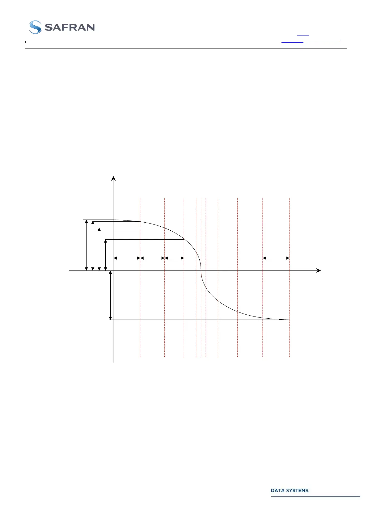
Frequency
Time
F0 = forward
programmed frequency
T1 T2 T3 Tn
IRIG-B Time reference
(Initialization request)
F0
F1
F2
F3
Fn
Figure 86: Doppler Variations for a LEO Spacecraft Pass
The above picture shows typical Doppler variations during a LEO satellite pass. The maximum Doppler is
observed at low elevation (horizon) while the maximum Doppler rate is observed at zenith pass.
Next figure shows the reconstructed frequency curve by the CORTEX with low distortion of the high Doppler rate
area due to the use of a higher sampling rate ().