COMMAND RANGING & TELEMETRY UNIT CORTEX
CRT QUANTUM USER'S MANUAL
Ref. DTU 100042
Is.Rev. 5.17
Date: Dec.
03, 2021Sept. 30, 2021
This document is the property of Safran Data Systems.
It cannot be duplicated or distributed without expressed written consent.
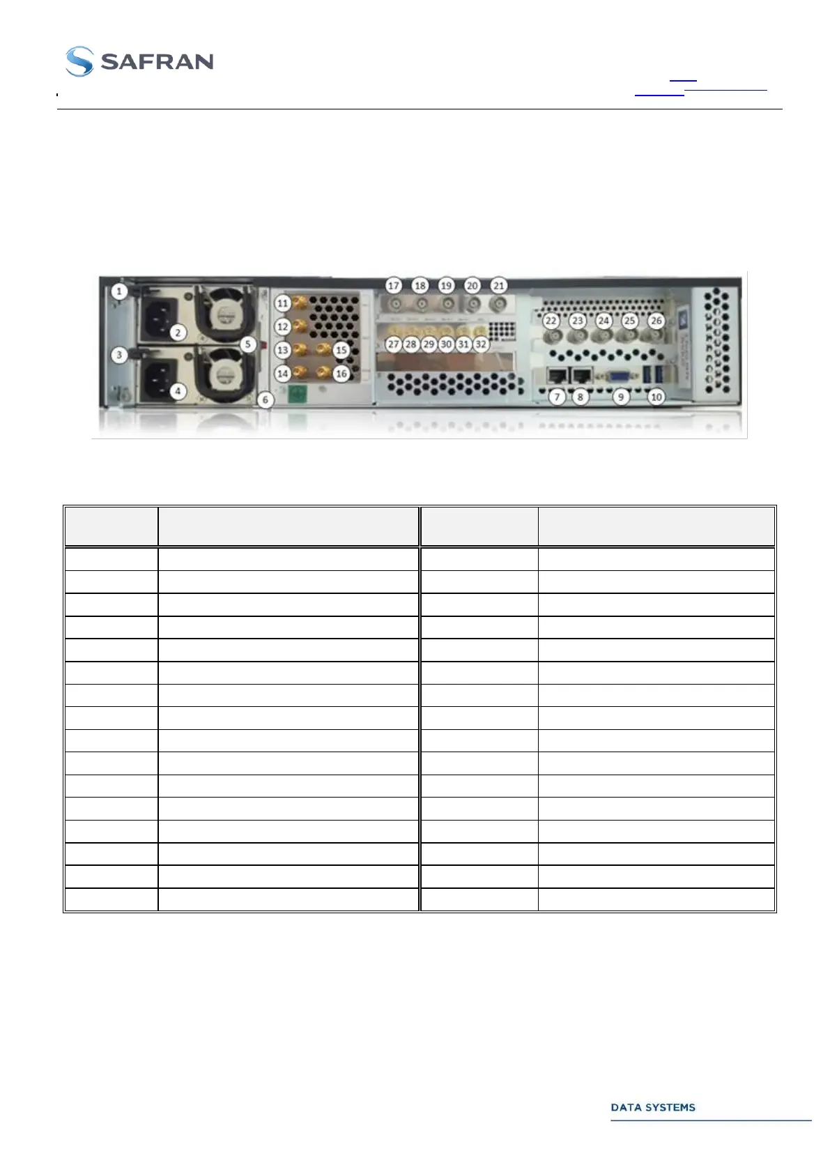
2.3.3.2.3. Configuration S100686: COMSAT 2U with EFC
The connection of the various signals to the user system is directly performed on the chassis rear panel as
described in 2.3.1.1. The computer connections (LAN, VGA) are directly available on the Industrial Computer
rear panel. The picture below lists and identifies the various connections to the computer ports, and the I/O
connectors of the Cortex CRT Quantum dedicated hardware.
Figure 18: Configuration S100686 Rear panel Connectors
Table 12: Configuration S100686 Rear panel Connectors
Upper power supply unlock system
Upper power supply AC input
Lower power supply unlock system
Downlink – IF Alternate 1
Lower power supply AC input
Downlink – IF Alternate 2
Power supply Sound Alarm Button
Downlink – IF Alternate 3
Downlink – RF / IF Nominal 1
Downlink – RF / IF Nominal 2
Downlink – RF / IF Nominal 3
Uplink – RF / IF Nominal 1
Uplink – RF / IF Nominal 2